TMC8462 Datasheet • Document Revision V1.4 • 2018-May -09
166 / 204
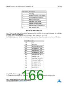
Status bit Description
7
6
5
4
3
2
1
0
Error Flag
Not Acknowledge received/sent
Acknowledge received/sent
Write to slave mode
Read from Slave mode
Transmit Address mode
Repeated Start condition sent
Start condition sent
Table 200: I2C status register bits
Bits 0 and 1 are set after command 0x20 was successfully executed, either if the I2C bus was idle or a start
condition already has been sent.
A combination of Bits 2 to 6 indicates completion of an address or data cycle.
Bit 7 indicates an error during transmission. A stop condition should be sent to return to the idle state.
Status byte Status
0x00
0x01
0x02
0x34
0x2C
0x54
0x4C
0xE4
0x48
0x28
0x30
0x50
0xF0
0xFF
Idle
Start sent
Repeated Start sent
Write Address ACK
Read Address ACK
Write Address NACK
Read Address NACK
Address Error
Read Data ACK sent
Read Data NACK sent
Write Data ACK
Write Data NACK
Write Data Error
General Error
Table 201: I2C status overview
I2C_ADDR – Address register with R/nW bit
This register contains the 7 bit address of the I2C slave and the single R(ead)/n(ot)W(rite) bit.
©2018 TRINAMIC Motion Control GmbH & Co. KG, Hamburg, Germany
Terms of delivery and rights to technical change reserved.
Download newest version at www.trinamic.com

 TRINAMIC [ TRINAMIC MOTION CONTROL GMBH & CO. KG. ]