TMC8462 Datasheet • Document Revision V1.4 • 2018-May -09
170 / 204
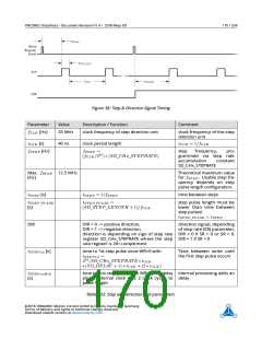
Figure 38: Step & Direction Signal Timing
Parameter
Value
Description / Function
Comment
fCLK [Hz]
25 MHz
clock frequency of step direction unit
clock frequency of the step
direction unit
tCLK [s]
40 ns
clock period length
tCLK = 1/fCLK
fST EP [Hz]
fST EP
=
step
frequency,
pro-
(fCLK/232) ∗ (SD_CHx_STEPRATE)
grammed via step rate
accumulation
SD_CHx_STEPRATE
constant
Max. fST EP 12.5 MHz
[Hz]
Theoretical maximum value
for fST EP . Usable step fre-
quency depends on step
pulse length configuration.
tST EP [s]
tST EP = 1/fST EP
tST EP _P ULSE
(SD_STEP_LENGTH + 1)/fCLK
time between steps
tST EP _P ULSE
[s]
=
step pulse length must be
lower than time between
step pulses!
tST EP _P ULSE < tST EP
DIR
DIR = 0 –> positive direction,
DIR = 1 –> negative direction,
direction signal, depending
of step rate (SR) parameter,
direction is depending on sign of step rate DIR = 0 if SR > 0 or SR = 0,
register SD_CHx_STEPRATE where the step DIR = 1 if SR < 0
rate register is 2th complement
tST EP 1st [s]
time to 1st step pulse since WR=0 with
Time between write until
the first step pulse occurs
tST EP 1st
=
232/SD_CHx_STEPRATE ∗ tCLK
+(SD_DELAY + 1) ∗ tCLK + (2 ∗ tCLK
)
tST EP 1stW R
[s]
time to first step pulse since WR=0 step delay Internal processing adds an
plus 1 internal clock plus 2 clock cycles to delay
pulse length
Table 203: Step and direction unit parameters
©2018 TRINAMIC Motion Control GmbH & Co. KG, Hamburg, Germany
Terms of delivery and rights to technical change reserved.
Download newest version at www.trinamic.com

 TRINAMIC [ TRINAMIC MOTION CONTROL GMBH & CO. KG. ]