TMC8462 Datasheet • Document Revision V1.4 • 2018-May -09
169 / 204
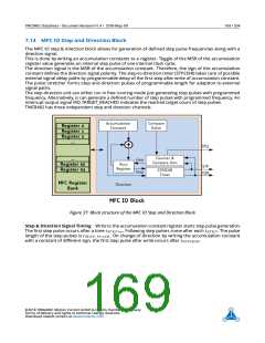
7.14 MFC IO Step and Direction Block
The MFC IO step & direction block allows for generation of defined step pulse frequencies along with a
direction signal.
This is done by writing an accumulation constants to a register. Toggle of the MSB of the accumulation
register value generates an internal step pulse of one internal clock cycle.
The direction signal is the MSB of the accumulation constant. Therefore, the sign of the accumulation
constant defines the direction signal polarity. The step-to-direction timer (STP2DIR) takes care of possible
external signal delay paths by programmable delay of the first step after write of accumulation constant.
The pulse stretcher forms step and direction pulses of programmable length for adaption to external
signal paths.
The step direction unit can either run in free running mode just generating step pulses with programmed
frequency. Alternatively, is can generate a defined number of step pulses with programmed frequency. An
interrupt output signal IRQ TARGET_REACHED indicates the reached target count of step pulses.
TMC8462 has three independent step and direction channels.
Figure 37: Block structure of the MFC IO Step and Direction Block
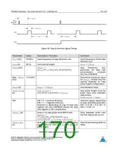
Step & Direction Signal Timing Write to the accumulation constant register starts step pulse generation.
The first step pulse occurs after a time tST EP 1st. Following step pulses come after each tST EP . The pulse
length of the step pulses is tST EP _P ULSE. On change of direction by writing the accumulation constant
with a constant of different sign, the first step pulse after write occurs after tST P 2DIR
.
©2018 TRINAMIC Motion Control GmbH & Co. KG, Hamburg, Germany
Terms of delivery and rights to technical change reserved.
Download newest version at www.trinamic.com

 TRINAMIC [ TRINAMIC MOTION CONTROL GMBH & CO. KG. ]