TMC8462 Datasheet • Document Revision V1.4 • 2018-May -09
165 / 204
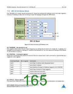
7.13 MFC IO I2C Master Block
The TMC8462 I2C master allows accessing I2C slaves by writing and reading control and data registers
instead of needing to take care of timing or even bit-banging through the GPIO block.
Figure 36: Block structure of SPI Master Unit
I2C_TIMEBASE – Bit duration in µs
This register determines the I2C clock frequency by setting the duration of a single bit. A setting of 0
disables communication, a setting of 1 results in bit duration of 1
in a bit duration of 255 µs.
µs, the maximum setting of 255 results
I2C_CONTROL – Command register
There are 6 commands that allow full control of the I2C master block. Each command is represented by a
single bit in this register.
Command byte Bit in register Command
0x20
0x10
0x08
0x04
0x02
0x01
5
4
3
2
1
0
Send Start Condition (also Repeated Start)
Send Stop Condition
Send Address (Content of Address register), incl. R/nW Bit
Send Data (Content of Data register)
receive Data and send ACK
receive Data and send NACK
Table 199: I2C control commands
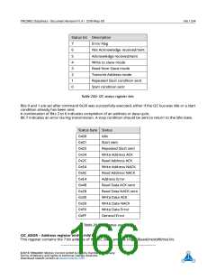
I2C_STATUS – Status register
The status bits show the current transmission status either alone or in a combination of multiple bits.
©2018 TRINAMIC Motion Control GmbH & Co. KG, Hamburg, Germany
Terms of delivery and rights to technical change reserved.
Download newest version at www.trinamic.com

 TRINAMIC [ TRINAMIC MOTION CONTROL GMBH & CO. KG. ]