UCD90320
www.ti.com.cn
ZHCSFI3B –AUGUST 2016–REVISED MAY 2019
7.7 I2C/PMBus Interface Timing Requirements
MIN
450
450
NOM
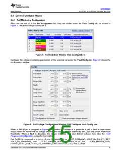
MAX
UNIT
ns
I1
I2
I3
I4
I5
I6
I7
I8
I9
I10
t(HD:STA)
t(LOW)
tr
Start condition hold time
Clock low period(1)
Clock rise time and data rise time(2)
ns
See(2)
125
ns
t(HD:DAT)
tf
Data hold time
25
ns
Clock fall time and data fall time(3)
Clock high time
112.5
ns
t(HIGH)
t(SU:DAT)
t(SU:STA)
t(SU:STO)
t(DV)
300
225
450
300
ns
Data setup time
ns
Start condition setup time (repeated start only)
Stop condition setup time
Data valid
ns
ns
25
ns
(1) PMBus host must support clock stretching per PMBus Power System Management Protocol Specification Part I General Requirements,
Transport and Electrical Interface, Revision 1.2, Section 5.2.6.
(2) Because the I2CSCL signal and the I2CSDA signal operate as open-drain-type signals, which the controller can actively drive only
"Low", the time that either signal takes to reach a high level depends on external signal capacitance and pull-up resistor values.
(3) Specified at a nominal 50-pF load.
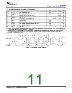
I2
I10
I6
I5
I2CSCL
I2CSDA
I1
I7
I8
I3
I9
I4
Figure 1. I2C/PMBus Timing Diagram
Copyright © 2016–2019, Texas Instruments Incorporated
11

 TI [ TEXAS INSTRUMENTS ]