UCD90320
www.ti.com.cn
ZHCSFI3B –AUGUST 2016–REVISED MAY 2019
8 Detailed Description
8.1 Overview
Electronic systems such as CPU, DSP, microcontroller, FPGA, and ASIC can have multiple voltage rails and
require certain power-ON and power-OFF sequences in order to function correctly. The UCD90320 device can
control up to 32 voltage rails and ensure correct power sequences during normal condition and fault conditions.
In addition to sequencing, the device can continuously monitor rail voltages, currents, temperatures, fault
conditions, and report the system health information to upper computers through a PMBus interface, improving
long term reliability.
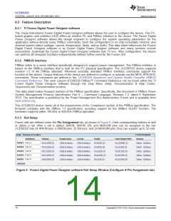
The device can protect electronic systems by responding to power system faults. The fault responses are
conveniently configured by users through Fusion Digital Power Designer software . Fault events are stored in on-
chip nonvolatile flash memory in order to assist failure analysis. A Black Box Fault Log feature stores
comprehensive system statuses at the moment when the first fault occurs. With this feature, failure analysis can
be more effective.
System reliability can be improved through four-corner testing during system verification. During four-corner
testing, each voltage rail is required to operate at the minimum and maximum output voltages, commonly known
as margining. The device can perform accurate closed-loop margining for up to 24 voltage rails. During normal
operation, UCD90320 can also actively trim DC output voltages using the same margining circuitry. This feature
allows tuning rail voltages to an optimal level.
The UCD90320 device supports control environments via both PMBus interface and pin-based interface. The
device functions as a PMBus slave. It can communicate with upper computers with PMBus commands, and
control voltage rails accordingly. In addition to rail enable (EN) pins, up to 32 GPIO pins can be configured as
GPOs and directly controlled by PMBus commands. The device can be controlled by up to 32 GPIO configured
GPI pins. The GPIs can be used as fault inputs which can shut down rails. The GPIs can be also used as
Boolean logic input to control the 16 Logic GPO outputs. Each of the 16 Logic GPO pins has a flexible Boolean
logic builder. Input signals of the Boolean logic builder can include GPIs, other GPOs, and selectable system
flags such as POWER_GOOD, faults, warnings, and so forth. A simple state machine is also available for each
Logic GPO pin.
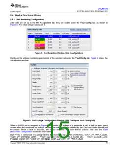
The device provides additional features such as cascading, pin-selected states, system watchdog, system reset,
run time clock, peak value log, reset counter, and so forth. Cascading feature offers convenient ways to cascade
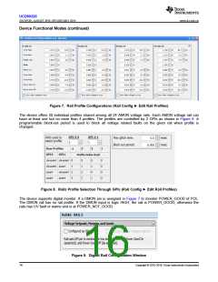
up to 4 UCD90320 devices and manage up to 128 voltage rails through one SYNC_CLK pin connection. Pin-
selected states feature allows users to define up to 8 rail states. These states can implement system low-power
modes as set out in the Advanced Configuration and Power Interface (ACPI) specification. The Feature
Description section of this datasheet describes other device features.
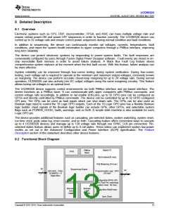
8.2 Functional Block Diagram
Digital I/O
PMBus
Slave
JTAG
Rail Enables(32 max)
Rail Margining (24 max)
32
Sequencing Engine
84
24ch ADC (12bit,
2x1MSPS) + 8
Digital Mon
Programmable Logic GPO
(16 max)
Configurable GPIO( GPI,
GPO, Fault Pin, watchdog/
system reset, 32 max)
Boolean
Logic
Builder
Nonvolatile
Event
Logging
Digital Mon Rail(8 max)
Sync Clock
Copyright © 2016–2019, Texas Instruments Incorporated
13

 TI [ TEXAS INSTRUMENTS ]