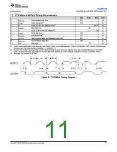
UCD90320
www.ti.com.cn
ZHCSFI3B –AUGUST 2016–REVISED MAY 2019
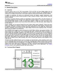
8.4 Device Functional Modes
8.4.1 Rail Monitoring Configuration
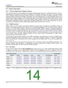
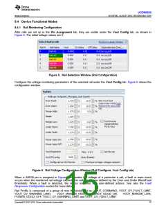
After rails are set up in the Pin Assignment tab, they are visible under the Vout Config tab, as shown in
Figure 5. The initial voltage values are 0.
Figure 5. Rail Selection Window (Rail Configuration)
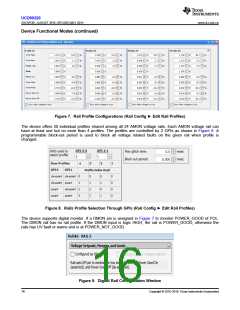
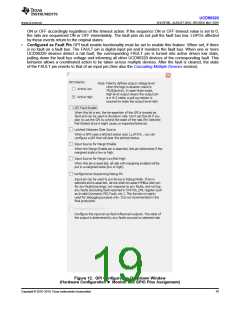
Configure the voltage monitoring parameters of the selected rail under the Vout Config tab. Figure 6 shows the
configuration window..
Figure 6. Rail Voltage Configuration Window (Rail Configure, Vout Config tab)
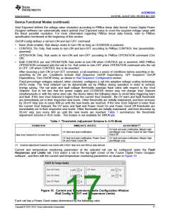
When a AMON pin is assigned in Figure 4 to monitor the voltage of a particular a rail, a fault or warn event
occurs when the monitored rail voltage exceeds the voltage window defined by the Over and Under Warn/Fault
thresholds. When a fault is detected, the device responds with user-defined actions. See also the Fault
Responses Configuration section for more details.
Rail Profile is composed of a group of nine thresholds set by: VOUT_COMMAND, VOUT_OV_FAULT_LIMIT,
VOUT_OV_WARNING_LIMIT,
VOUT_MARGIN_HIGH,
POWER_GOOD_ON,
VOUT_MARGIN_LOW,
POWER_GOOD_OFF, VOUT_UV_WARNING_LIMIT and VOUT_UV_FAULT_LIMIT.
Copyright © 2016–2019, Texas Instruments Incorporated
15

 TI [ TEXAS INSTRUMENTS ]