UCD90320
ZHCSFI3B –AUGUST 2016–REVISED MAY 2019
www.ti.com.cn
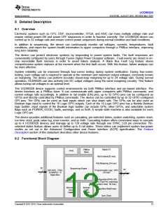
8.3 Feature Description
8.3.1 TI Fusion Digital Power Designer software
The Texas Instruments Fusion Digital Power Designer software allows the user to configure the device. This PC-
based graphic user interface (GUI) offers an intuitive I2C and PMBus interface to the device. The Fusion Digital
Power Designer software allows the design engineer to configure the system operating parameters for the
application without directly using PMBus commands, store the configuration to on-chip nonvolatile memory, and
observe system status (voltage, current, temperature, faults, and so forth). This data sheet references the Fusion
Digital Power Designer software is as Fusion Digital Power Designer software and many sections include
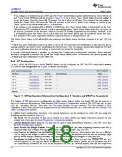
screenshots. Download the Fusion Digital Power Designer software from TI here. After configuration, the device
can perform all designed functions independently without further need for the Fusion GUI.
8.3.2 PMBUS Interface
PMBus refers to a serial interface specifically designed to support power management. The PMBus interface is
based on the SMBus interface that is built on the I2C physical specification. The UCD90320 device supports
revision 1.2 of the PMBus standard. Wherever possible, standard PMBus interface commands support the
function of the device. Unique features of the device are defined to configure or activate via the MFR_SPECIFIC
commands. These commands are defined in the, UCD90320 Sequencer and System Health Controller PMBUS
Command Reference. The most current UCD90320 PMBus™ Command Reference can be found within the TI
Fusion Digital Power Designer software through the Help Menu (Help, Documentation & Help Center,
Sequencers tab, Documentation section).
This data sheet makes frequent mention of the PMBus specification. Specifically, this document is PMBus Power
System Management Protocol Specification Part II – Command Language, Revision 1.2, dated 6 September
2010. The specification is published by the Power Management Bus Implementers Forum and is available from
www.pmbus.org.
The UCD90320 device meets all of the requirements of the Compliance section of the PMBus specification. The
firmware complies with the SMBus 1.2 specification, including support for the SMBus ALERT function. The
hardware supports either 100-kHz or 400-kHz PMBus operation.
8.3.3 Rail Setup
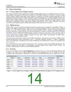
Power rails are defined under the Pin Assignment tab, as shown in Figure 4. Click corresponding buttons to add
or delete a rail. After a rail is added, AMON, DMON, EN, and MARGIN pins can be assigned to the rail.
UCD90320 has 24 AMON pins, 8 DMON pins, 32 EN pins, and 24 MARGIN pins, thus can support up to 32 rails.
Figure 4. Fusion Digital Power Designer software Rail Setup Window (Configure ►Pin Assignment tab)
14
Copyright © 2016–2019, Texas Instruments Incorporated

 TI [ TEXAS INSTRUMENTS ]