ꢀ ꢁꢁꢂ ꢃ ꢄ ꢅ ꢆ ꢀ ꢁ ꢁꢂ ꢃ ꢄ ꢇ ꢆ ꢀꢁ ꢁꢂ ꢃ ꢄ ꢄ
ꢀ ꢁꢁꢈ ꢃ ꢄ ꢅ ꢆ ꢀ ꢁ ꢁꢈ ꢃ ꢄ ꢇ ꢆ ꢀꢁ ꢁꢈ ꢃ ꢄ ꢄ
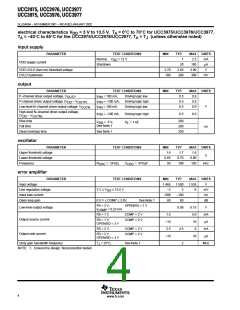
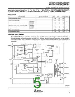
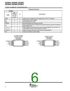
SLUS499A – NOVEMBER 2001 – REVISED JANUARY 2002
state diagram
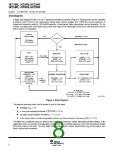
A logic state diagram for the UCC397x family of controllers is shown in Figure 5. During power-up the controller
transitions from UVLO to the momentary startup state. During startup, the COMP pin is preconditioned at
maximum frequency and the OPEN/SD capacitor is discharged before beginning normal operation. In the
normal operating state, the frequency is swept from high to low allowing the lamp to be struck and the current
in the lamp to be regulated.
ERROR
SHUTDOWN
YES
Increment COUNT
COUNT=7?
OSC active
OUT off state
* Momentary states
NO
UVLO
STARTUP *
NO–LOCK *
VDD>3.0V
VDD < 3.0V
OSC inactive
OUT off state
COUNT=0
OPEN/SD = 0V
COMP = 0V
OSC, OUT active
COMP > 2.5V
OPEN/SD < 1.5V
OSC, OUT active
SHUTDOWN
OPEN/SD > 2.5V
COUNT =0
NORMAL OPERATION
OPEN LAMP *
OSC inactive
OUT off state
Low current VDD,
OPEN/SD
OPEN/SD < 1.5V
COMP < 2.5V
OSC, OUT active
1.5V < OPEN/SD <2.5V
COMP < 2.5V
OPEN/SD
< 0.5V
OSC, OUT active
OUT off state
UCC3975: OUT1 low, OUT2 low
UCC3976: OUTP high, OUTN high
UCC3977: OUT1 low, OUT2 low
UDG–01102
Figure 5. State Diagram
The normal operating state can be exited in one of four ways:
•
•
•
•
bringing V
< 3 V
DD
a user commanded shutdown (OPEN/SD > 2.5 V)
an open lamp condition (OPEN/SD > 1.5 V), or
if the device fails to achieve regulation before reaching minimum frequency (EAO > 2.5 V).
The latter two conditions cause an internal retry counter to increment before attempting another startup. If the
application does not operate normally after seven retrys, the controller enters an error induced shutdown state
removing power to the load. The error state and counter can be cleared by removing V
user commanded shutdown.
to the part or by a
DD
8
www.ti.com

 TI [ TEXAS INSTRUMENTS ]