ꢀꢁꢁ ꢂ ꢃꢄ ꢅ ꢆ ꢀꢁꢁ ꢂ ꢃꢄ ꢇ ꢆ ꢀ ꢁꢁ ꢂꢃ ꢄꢄ
ꢀꢁꢁ ꢈ ꢃꢄ ꢅ ꢆ ꢀꢁꢁ ꢈ ꢃꢄ ꢇ ꢆ ꢀ ꢁꢁ ꢈꢃ ꢄꢄ
SLUS499A – NOVEMBER 2001 – REVISED JANUARY 2002
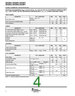
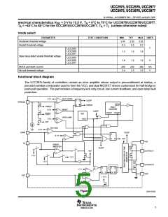
electrical characteristics V
A
= 3 V to 13.5 V, T = 0°C to 70°C for UCC3975/UCC3976/UCC3977,
A
DD
T = –40°C to 85°C for the UCC2975/UCC2976/UCC2977, T = T (unless otherwise noted)
A
J
mode select
PARAMETER
TEST CONDITIONS
MIN
2.45
TYP
2.50
MAX
2.65
0.7
UNITS
Shutdown threshold voltage
Restart threshold voltage
0.3
0.5
V
UCC2975
UCC2976
UCC2977
1.3
1.5
1.6
1.6
Open lamp detect enable threshold voltage
UCC3975
UCC3976
UCC3977
1.4
1.5
V
MODE pull-down current
No lock threshold voltage
200
2.4
250
2.5
300
2.6
mA
V
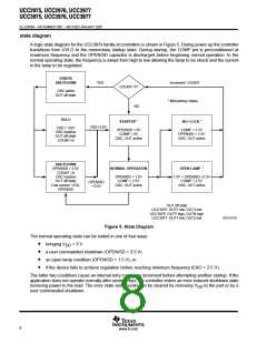
functional block diagram
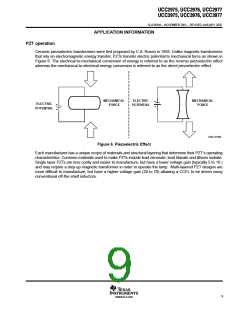
The UCC397x family of controllers contain an error amplifier whose output is preconditioned at startup, a
precision window comparator used to form the VCO, and dual MOSFET drivers customized for half-bridge or
push-pull operation. The part includes a frequency lock retry circuit, low current shutdown, and open lamp fault
protection.
2.5 V
SHUT DOWN
S
R
Q
Q
SLEEP
OPEN/SD
+
+
PWRUP
FAULT
FAULT
COUNTER
PWRUP
0.5 V
RESET
SLEEP
RESET COUNT
REF
UVLO
FAULT
OPEN LAMP
1.5 V
INIT
+
NO LOCK
0.1 V
2.5 V
COMP
FB
SLEEP
+
R
+
INIT
S
Q
VDD
ERROR
AMPLIFIER
SLEEP
INIT
OUTP/OUT1
+
1.5 V
1.5 V
1.4 V
OUTN/OUT2
GND
D
Q
Q
R
S
1.7 V
0.7 V
+
+
Q
CK
OSC
1.75 V
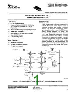
Figure 4
UDG–01053
5
www.ti.com

 TI [ TEXAS INSTRUMENTS ]