ꢀ ꢁꢁꢂ ꢃ ꢄ ꢅ ꢆ ꢀ ꢁ ꢁꢂ ꢃ ꢄ ꢇ ꢆ ꢀꢁ ꢁꢂ ꢃ ꢄ ꢄ
ꢀ ꢁꢁꢈ ꢃ ꢄ ꢅ ꢆ ꢀ ꢁ ꢁꢈ ꢃ ꢄ ꢇ ꢆ ꢀꢁ ꢁꢈ ꢃ ꢄ ꢄ
SLUS499A – NOVEMBER 2001 – REVISED JANUARY 2002
APPLICATION INFORMATION
lamp characteristics
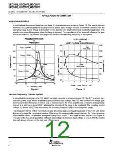
A cold cathode fluorescent lamp has non-linear V-I characteristics as shown in Figure 10. The lamp’s intensity
(lumens) is roughly proportional to lamp current where lamp voltage remains somewhat constant over the
operating range. Lamp voltage is dependant on the diameter and length of the lamp used in the application. This
results in increased impedance when the lamp is dimmed. The impedance of the lamp will influence the gain
of the piezoelectric transformer (see Figure 9) and thus the operating frequency of the system.
PIEZOELECTRIC GAIN
CCFL CURRENT
vs
vs
FREQUENCY
LAMP VOLTAGE AND IMPEDANCE
300
250
200
150
100
50
800
750
700
650
600
550
3000
2500
2000
1500
1000
500
LAMP
VOLTAGE
R
= 750 kΩ
OUT
R
= 500 kΩ
OUT
strike
B
LAMP
R
= 250 kΩ
OUT
IMPEDANCE
R
= 100 kΩ
OUT
start
C
A
operate
500
0
0
1
2
3
4
5
6
0
60
65
70
75
80
I
– Lamp Current – mA
LAMP
f – Frequency – kHz
Figure 10
Figure 9
variable frequency control system
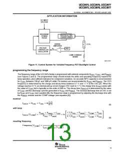
A simplified block diagram of a PZT based backlight converter is shown in Figure 11. The PZT is driven by a
resonant power stage whose amplitude is proportional to input voltage. The PZT then provides the voltage gain
necessary to drive the lamp. A control loop is formed around the error amplifier that compares average lamp
current to a reference signal (REF) allowing the intensity of the lamp to be regulated. The resulting control
voltage V drives a VCO that determines the operating frequency of the resonant power stage.
C
The frequency range of the VCO must include the strike and operating frequencies of the PZT with some
tolerance included for component variation. Minimizing the programmable range improves the control response
of the feedback loop. For example, a frequency range of 67 kHz to 77 kHz might be used for the PZT in Figure 9.
The gain of the PZT must guarantee sufficient lamp voltage at minimum input voltage to ensure that the control
loop will always operate on the right side of resonance.
12
www.ti.com

 TI [ TEXAS INSTRUMENTS ]