ꢀ ꢁꢁꢂ ꢃ ꢄ ꢅ ꢆ ꢀ ꢁ ꢁꢂ ꢃ ꢄ ꢇ ꢆ ꢀꢁ ꢁꢂ ꢃ ꢄ ꢄ
ꢀ ꢁꢁꢈ ꢃ ꢄ ꢅ ꢆ ꢀ ꢁ ꢁꢈ ꢃ ꢄ ꢇ ꢆ ꢀꢁ ꢁꢈ ꢃ ꢄ ꢄ
SLUS499A – NOVEMBER 2001 – REVISED JANUARY 2002
APPLICATION INFORMATION
VOUT
PRIMARY
FORCE
SECONDARY
VIN
FORCE
h = HEIGHT
T = THICKNESS
SUPPORTS
L = LENGTH
MECHANICAL
DISPLACEMENT
0
0
MECHANICAL
STRESS
UDG–01076
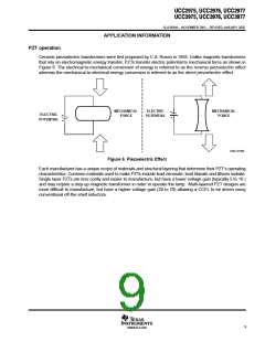
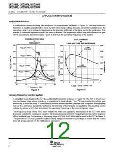
Figure 7. Typical Longitudinal Mode Piezoelectric Transformer for CCFL Applications.
A typical multi-layer PZT with longitudinal mode geometry is shown in Figure 7, a single layer design would have
similar construction without the layering on the primary. An ac voltage is applied to the V electrodes causing
IN
mechanical expansion and compression in the thickness direction (see Figure 6). This displacement on the
primary is transferred as a force in the longitudinal direction. Supports at ¼ and ¾ wavelength provide a means
for a standing wave to be generated at a resonant frequency as shown. Mechanical resonance occurs at
multiple standing wave frequencies (n) based on the transformer’s length and material velocity (v).
v
f + n
n
2 length
(1)
Voltage gain is a function of the PZT material coefficient g[ω], the number of primary layers, the thickness of
the material and the overall length as follows:
length layers
[ ]
g w
V
+
GAIN
thickness
(2)
An electrode at V
is used to recover the amplified electrical potential at the secondary.
OUT
PZT electrical model
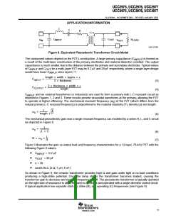
In order to predict PZT performance in a system, it is useful to develop an electrical circuit model. The model
shown in Figure 8 is often used to describe the behavior of a PZT near the fundamental resonant frequency.
Many PZT manufacturers will provide component values for the model based on measurements taken at
various frequencies and output loads.
10
www.ti.com

 TI [ TEXAS INSTRUMENTS ]