ꢀꢁꢁ ꢂ ꢃꢄ ꢅ ꢆ ꢀꢁꢁ ꢂ ꢃꢄ ꢇ ꢆ ꢀ ꢁꢁ ꢂꢃ ꢄꢄ
ꢀꢁꢁ ꢈ ꢃꢄ ꢅ ꢆ ꢀꢁꢁ ꢈ ꢃꢄ ꢇ ꢆ ꢀ ꢁꢁ ꢈꢃ ꢄꢄ
SLUS499A – NOVEMBER 2001 – REVISED JANUARY 2002
APPLICATION INFORMATION
L
C
R
1 : n
C
C
R
OUT
INPUT
V
IN
V
OUT
LOAD
UDG–01100
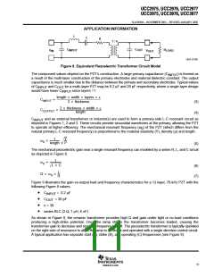
Figure 8. Equivalent Piezoelectric Transformer Circuit Model
The component values depend on the PZT’s construction. A large primary capacitance (C
) is formed as
INPUT
a result of the multi-layer construction of the primary electrodes and material dielectric constant. The output
capacitance is much smaller due to the distance between the primary and secondary electrodes. Typical values
of C
and C
for a multi–layer PZT may be 0.2 µF and 20 pF respectively, where a single layer design
INPUT
OUT
would have lower C
since layers =1.
INPUT
length width layers å
C
C
+
INPUT
2 thickness
(3)
(4)
2 thickness width å
+
OUTPUT
length
C
and an external transformer or inductor(s) are used to form a primary-side L-C resonant circuit as
INPUT
depicted in Figures 1, 2 and 3. These circuits provide sinusoidal waveforms at the primary, allowing the PZT
to operate at higher efficiency. The mechanical resonant frequency (ω ) of the PZT (which differs from the
0
natural primary L-C resonant frequency) is proportional to the material elasticity (Y), density (ρ) and length.
1
Y
ò
Ǹ
w T
0
length
(5)
The mechanical piezoelectric gain near a single resonant frequency can modeled by a series R, L, and C circuit
as depicted in Figure 8.
1
w +
0
Ǹ
L C
(6)
(7)
L
R
Q + w
0
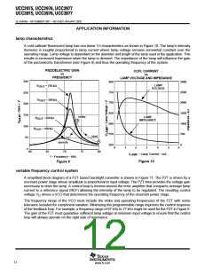
Figure 9 illustrates the gain-vs-output load and frequency characteristics for a 12-layer, 70-kHz PZT with the
following Figure 8 values:
•
•
•
•
C
= 0.2 µF
INPUT
C
= 30 pF
OUT
n = 30
series RLC (2 Ω, 1 µH, 6 nF)
As shown in Figure 9, the ceramic transformer provides high Q and gain under light or no-load conditions
producing a high-strike potential. Once the lamp strikes the transformer becomes loaded, causing the
transformer gain to decrease and resonant frequency to shift. The piezoelectric transformer is typically operated
on the right side of resonance to allow the lamp to be struck and operated with a single direction control circuit.
A typical application has separate start (A), strike (B), and operating (C) frequencies (see Figure 9).
11
www.ti.com

 TI [ TEXAS INSTRUMENTS ]