ꢀꢁꢁ ꢂ ꢃꢄ ꢅ ꢆ ꢀꢁꢁ ꢂ ꢃꢄ ꢇ ꢆ ꢀ ꢁꢁ ꢂꢃ ꢄꢄ
ꢀꢁꢁ ꢈ ꢃꢄ ꢅ ꢆ ꢀꢁꢁ ꢈ ꢃꢄ ꢇ ꢆ ꢀ ꢁꢁ ꢈꢃ ꢄꢄ
SLUS499A – NOVEMBER 2001 – REVISED JANUARY 2002
APPLICATION INFORMATION
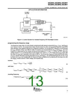
half-bridge operation and inductor selection
In the half-bridge topology, the external inductor and piezoelectric capacitance form a low-pass filter between
the common switch node of the external MOSFETs and the piezoelectric primary as shown on the front page.
The L-C filter formed by these components should pass the resonant frequency, required by the piezoelectric
transformer, yet attenuate higher harmonic components. The choice of inductor will require bench
measurements and modeling of the resonant circuit:
•
•
•
An inductor value that is too low (high L-C resonant frequency) will result in non-sinusoidal primary
waveforms since higher order harmonics are allowed though the filter. A low value also allows excess
circulating currents, impacting efficiency.
An inductor value that results in a L-C resonant frequency close to the resonant frequency of the
piezoelectric transformer causes interference, making control of the primary voltage difficult. The
interference occurs since the gain of the L-C tank depends heavily on load in this region of operation.
An inductor value that is too large causes an attenuation of the input voltage, increasing the gain
requirements of the piezoelectric transformer and/or the system.
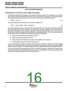
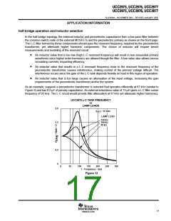
As an example, suppose a piezoelectric transformer is selected that operates efficiently at 67 kHz (similar to
Figure 9) and has 0.2-µF of primary capacitance. An external inductance value of 15 µH gives a L-C filter corner
frequency of 92 kHz. The L-C circuit would provide little attenuation at 67 kHz yet attenuate higher harmonics.
UCC3976 L-C TANK FREQUENCY
vs
LAMP LOADS
2.0
f
= 67 kHz
PZT
LAMP LOAD
150 kΩ
100 kΩ
50 kΩ
1.5
1
0.5
0
0
50
100
150
200
250
300
f – Frequency – kHz
Figure 13
17
www.ti.com

 TI [ TEXAS INSTRUMENTS ]