ꢀꢁꢁ ꢂ ꢃꢄ ꢅ ꢆ ꢀꢁꢁ ꢂ ꢃꢄ ꢇ ꢆ ꢀ ꢁꢁ ꢂꢃ ꢄꢄ
ꢀꢁꢁ ꢈ ꢃꢄ ꢅ ꢆ ꢀꢁꢁ ꢈ ꢃꢄ ꢇ ꢆ ꢀ ꢁꢁ ꢈꢃ ꢄꢄ
SLUS499A – NOVEMBER 2001 – REVISED JANUARY 2002
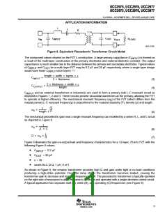
APPLICATION INFORMATION
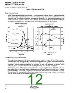
setting lamp current
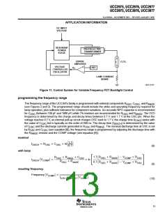
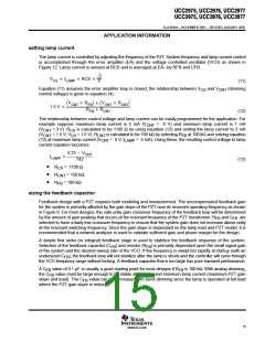
The lamp current is controlled by adjusting the frequency of the PZT. System frequency and lamp current control
is accomplished through the error amplifier (EA) and the voltage controlled oscillator (VCO) as shown in
Figure 12. Lamp current is sensed at RCS and is averaged at EA– by RFB and CFB.
Ǹ
2
V
+ I
RCS
CS
LAMP
p
(11)
Equation (11) assumes the error amplifier loop is closed, the relationship between V
and V
(dimming
CS
CNT
control voltageǒ)Vis given in equation (4).
Ǔ ) ǒV
Ǔ
R
R
CNT
FB
CNT
CNT
CNT
1.5 V +
R
) R
FB
(12)
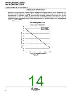
The relationship between control voltage and lamp current can be easily programmed for the application. For
example suppose maximum lamp current is 5 mA (V = 0 V) and minimum lamp current is 1 mA
CNT
(V
(V
= 3 V). R
= 1.5 V, V = 1.5 V). R
is calculated to be 1100 Ω by using equation (12) and setting the lamp current to 3 mA
CNT
CNT
CS
CS
is calculated to be 150 kΩ by selecting R at 100 kΩ and solving equation
FB
CNT
CNT
(12) at maximum lamp current (V
current equation becomes:
= 0 V, I
= 5 mA). Using these, the resulting control voltage to lamp
LAMP
3.75 * V
CNT
I
+
LAMP
742
(13)
•
•
•
R
= 1100 Ω
= 150 kΩ
CS
R
CNT
R
= 100 kΩ
FB
sizing the feedback capacitor
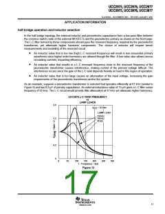
Feedback design with a PZT requires both modeling and measurement. The uncompensated feedback gain
for the system is primarily affected by the gain slope of the PZT near its resonant operating frequency as shown
in Figure 9. For most designs, the safe unity gain crossover frequency of the feedback loop will be determined
by the amount of gain peaking that occurs at the resonant frequency of the PZT transformer. R and C
are
FB
FB
selected to have a fairly low crossover frequency to ensure that the system gain does not increase above unity
at the resonant switching frequency. Since the gain slope is dependant on the lamp load and PZT model, it is
recommended that a network analyzer is used to validate sufficient gain and phase margin for the design.
A simple first order (or integral) feedback stage is used to stabilize the feedback response of the system.
Selection of the feedback capacitor (C ) and resistor (R ) is primarily dependant upon the small signal gain
FB
FB
of the system and the desired sweep rate of the VCO. If the frequency is swept too rapidly at startup (with an
undersized C ), the feedback loop will not stabilize after the lamp is struck and the controller will cycle through
FB
the VCO frequency range without locking. A feedback capacitor that is too large has poor transient performance.
A C value of 0.1 µF is usually a good starting point for most designs if R is 100 kΩ. With analog dimming,
FB
FB
the C value must be large enough to be stable at high V and minimum lamp current (maximum PZT gain
FB
IN
slope and load). The C value can be decreased with burst dimming since the lamp is operated at full load
FB
where the PZT gain slope is reduced.
15
www.ti.com

 TI [ TEXAS INSTRUMENTS ]