ꢀ ꢁꢁꢂ ꢃ ꢄ ꢅ ꢆ ꢀ ꢁ ꢁꢂ ꢃ ꢄ ꢇ ꢆ ꢀꢁ ꢁꢂ ꢃ ꢄ ꢄ
ꢀ ꢁꢁꢈ ꢃ ꢄ ꢅ ꢆ ꢀ ꢁ ꢁꢈ ꢃ ꢄ ꢇ ꢆ ꢀꢁ ꢁꢈ ꢃ ꢄ ꢄ
SLUS499A – NOVEMBER 2001 – REVISED JANUARY 2002
APPLICATION INFORMATION
matching the PZT to the lamp, input voltage and topology
A fundamental challenge in the design of a piezoelectric transformer-based CCFL application is to match the
lamp’s power requirements with the transformer. Since the piezoelectric transformer is a mechanical system,
the energy delivered by the transformer is a function of its mass and its vibrational velocity (ν).
2
energy T mass n
(14)
The power delivered by the transformer is described in equation (15):
d
dt
power + energy + energy frequency
(15)
The design challenge becomes how operate the transformer within its gain and power delivering capabilities
while optimizing overall system efficiency. This optimization requires knowledge of both the lamp and
piezoelectric transformer for the particular application. Achieving optimal efficiency with a given lamp and
piezoelectric transformer will require bench measurements and design iterations. There are several factors that
should be taken into consideration when selecting a piezoelectric transformer:
•
•
•
•
What is the recommended input voltage for the PZT?
What is the input capacitance of the PZT?
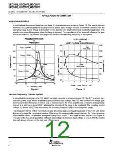
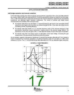
What is the gain of the transformer at various load conditions? (see Figure 9)
At what frequency does the PZT give maximum gain?
The recommended input voltage and gain of the piezoelectric transformer influence the power topology
selection. As mentioned earlier, the half-bridge topology gives the least gain where the push-pull topology
doubles the primary voltage. The flyback topology can provide additional gain through the flyback transformer.
The input capacitance and operating frequency of the piezoelectric transformer determines the required value
of the external inductor(s) (or transformer inductance in the case of the flyback). The external inductance value
may need to be further optimized to get the best performance.
16
www.ti.com

 TI [ TEXAS INSTRUMENTS ]