ꢀꢁꢁ ꢂ ꢃꢄ ꢅ ꢆ ꢀꢁꢁ ꢂ ꢃꢄ ꢇ ꢆ ꢀ ꢁꢁ ꢂꢃ ꢄꢄ
ꢀꢁꢁ ꢈ ꢃꢄ ꢅ ꢆ ꢀꢁꢁ ꢈ ꢃꢄ ꢇ ꢆ ꢀ ꢁꢁ ꢈꢃ ꢄꢄ
SLUS499A – NOVEMBER 2001 – REVISED JANUARY 2002
APPLICATION INFORMATION
push-pull operation and inductor selection
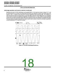
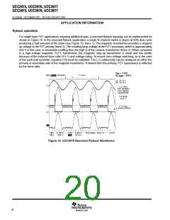
For the push-pull circuit, MOSFETs N1 and N2 are driven out of phase with 50% duty cycle at variable frequency
(see Figure 15: trace 2). Inductors L1 and L2 resonate with the PZT primary capacitance, forming a half
sinusoids at the drain of N1 (trace 1) and S2 (trace 4). The resulting voltage across the PZT primary is a near
sinusoid (trace M1). Due to the high Q of the ceramic transformer, the lamp voltage, which is approximately
600 V in this application, is sinusoidal (trace 3). In order to achieve zero-voltage switching, each drain voltage
must return to zero before the next switching cycle. This dictates that the L-C resonant frequency be greater
than the switching frequency. The maximum inductance to meet these conditions can be found from
equation (16):
1
L t
2
2
4 p f C
p
(16)
V
V
= 7 Vdc
IN
LAMP
= 600 V
Figure 15. UCC3977 Push-Pull Waveforms
19
www.ti.com

 TI [ TEXAS INSTRUMENTS ]