ꢀꢁꢁ ꢂ ꢃꢄ ꢅ ꢆ ꢀꢁꢁ ꢂ ꢃꢄ ꢇ ꢆ ꢀ ꢁꢁ ꢂꢃ ꢄꢄ
ꢀꢁꢁ ꢈ ꢃꢄ ꢅ ꢆ ꢀꢁꢁ ꢈ ꢃꢄ ꢇ ꢆ ꢀ ꢁꢁ ꢈꢃ ꢄꢄ
SLUS499A – NOVEMBER 2001 – REVISED JANUARY 2002
APPLICATION INFORMATION
DC INPUT
VOLTAGE
RESONANT
POWER
STAGE
PIEZOELECTRIC
TRANSFORMER
ERROR
AMPLIFIER
CCFL
VOLTAGE
CONTROLLED
OSCILLATOR
REF
+
V
C
–
LAMP CURRENT
SENSE
UDG–01101
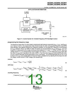
Figure 11. Control System for Variable Frequency PZT Backlight Control
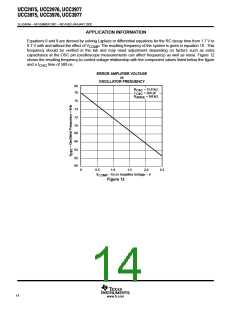
programming the frequency range
The frequency range of the UCC397x family is programmed with external components R
, C
, and R
OSC OSC ANGE
(see Figures 2 and 3). The programmed range should include the strike and operating frequency required for
lamp operation, plus sufficient tolerance for component variations. An accurate NPO capacitor is recommended
for C
(between 100 pF and 1000 pF) while 1% resistors are recommended for R
and R
. The VCO
OSC
OSC
ANGE
frequency is determined by the charge and decay times between 0.7 V and 1.7 V at the OSC pin. When the
voltage reaches 0.7 V, an internal pull-up circuit charges OSC back to 1.7 V, the charge time (t ) varies with
CHG
the value of C
but is typically on the order of 500 ns. The decay time (t
) is determined by the value
OSC
DISCH
of C
by R
the R
and the discharge currents generated in R
and C
and R
. The nominal discharge time at OSC is set
(see equation [8]), the frequency range is programmed by adjusting the discharge time with
OSC
OSC
OSC
ANGE
OSC
resistor and the COMP voltage (see equation [9]):
ANGE
nominal
1.7
lnǒ Ǔ
t
+ R
C
DISCH
OSC
OSC
0.7
(8)
with lamp
1.7 ǒR
Ǔ * V
) R
) R
R
R
R
R
C
OSC
OSC
ANGE
COMP
COMP
OSC
OSC
OSC
ANGE
OSC
ǒV
Ǔ +
t
ln
ƪ
ƫ
DISCH
COMP
R
) R
0.7 ǒR
Ǔ * V
OSC
ANGE
ANGE
(9)
resulting frequency
1
Frequency ǒV
Ǔ +
COMP
ǒV
Ǔ
t
) t
CHG
DISCH
COMP
(10)
13
www.ti.com

 TI [ TEXAS INSTRUMENTS ]