ꢀ ꢁꢁꢂ ꢃ ꢄ ꢅ ꢆ ꢀ ꢁ ꢁꢂ ꢃ ꢄ ꢇ ꢆ ꢀꢁ ꢁꢂ ꢃ ꢄ ꢄ
ꢀ ꢁꢁꢈ ꢃ ꢄ ꢅ ꢆ ꢀ ꢁ ꢁꢈ ꢃ ꢄ ꢇ ꢆ ꢀꢁ ꢁꢈ ꢃ ꢄ ꢄ
SLUS499A – NOVEMBER 2001 – REVISED JANUARY 2002
APPLICATION INFORMATION
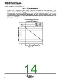
Equations 8 and 9 are derived by solving Laplace or differential equations for the RC decay time from 1.7 V to
0.7 V with and without the effect of V . The resulting frequency of the system is given in equation 10. This
COMP
frequency should be verified in the lab and may need adjustment depending on factors such as extra
capacitance at the OSC pin (oscilloscope measurements can affect frequency) as well as noise. Figure 12
shows the resulting frequency-to-control voltage relationship with the component values listed below the figure
and a t
time of 500 ns.
CHG
ERROR AMPLIFIER VOLTAGE
vs
OSCILLATOR FREQUENCY
80
78
R
C
R
= 15.8 kΩ
= 560 pF
OSC
OSC
= 162 kΩ
ANGE
76
74
72
70
68
66
64
62
60
0
0.5
1.0
1.5
2.0
2.5
V
– Error Amplifier Voltage – V
COMP
Figure 12
14
www.ti.com

 TI [ TEXAS INSTRUMENTS ]