ꢀꢁꢁ ꢂ ꢃꢄ ꢅ ꢆ ꢀꢁꢁ ꢂ ꢃꢄ ꢇ ꢆ ꢀ ꢁꢁ ꢂꢃ ꢄꢄ
ꢀꢁꢁ ꢈ ꢃꢄ ꢅ ꢆ ꢀꢁꢁ ꢈ ꢃꢄ ꢇ ꢆ ꢀ ꢁꢁ ꢈꢃ ꢄꢄ
SLUS499A – NOVEMBER 2001 – REVISED JANUARY 2002
APPLICATION INFORMATION
analog dimming PZT performance
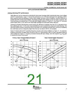
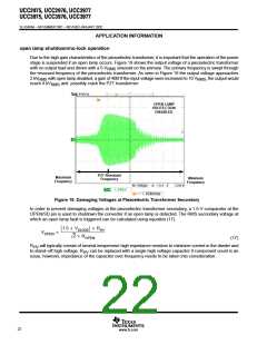
High efficiency can be achieved by selecting the best power topology while matching the lamp, input voltage
and PZT characteristics. Figure 17 shows the performance of a 3-W rated multi-layer PZT operating a 600 V
lamp using the push-pull topology at various input voltage and lamp current conditions. Electrical efficiency is
greater than 85% at lower input voltages, decreasing at higher input voltages as the PZT gain is reduced. This
circuit and lamp can operate from 2 Li-Ion cells with voltages between 5 V and 8.2 V. The same PZT and lamp
would require three Li–Ion cells for the half-bridge topology but would yield similar efficiency.
Dimming by linearly reducing lamp current causes the efficiency to degrade since the PZT is operated at less
than optimal gain (see 1.5 mA curve). Improved efficiency can be achieved by using burst mode dimming. This
dimming method involves running the lamp at full power, but controlling average lamp current by modulating
the on/off duty cycle at a frequency higher than the eye can detect (100 Hz, for example).
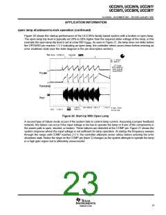
Figure 18 shows plots of PZT operating frequency over the same lamp conditions as Figure 17. As expected,
frequency decreases at higher lamp currents as the PZT characteristics shift to a lower operating frequency
when loaded (see Figure 2). Frequency increases linearly with input voltage, since the required V
to operate the lamp is decreased.
/V gain
OUT IN
TYPICAL PIEZO TRANSFORMER EFFICIENCY
PIEZO TRANSFORMER FREQUENCY
vs
vs
INPUT VOLTAGE
INPUT VOLTAGE
65.0
95
90
85
80
75
1.5 mA
570 V
64.5
64.0
63.5
3.0 mA
610 V
4.5 mA
570 V
63.0
62.5
62.0
61.5
61.0
60.5
3.0 mA
610 V
70
65
60
55
50
4.5 mA
570 V
1.5 mA
660 V
60.0
4
5
6
7
8
9
10
4
5
6
7
8
9
10
V
– Input Voltage – Vdc
V
– Input Voltage – Vdc
IN
IN
Figure 17
Figure 18
21
www.ti.com

 TI [ TEXAS INSTRUMENTS ]