ꢀ ꢁꢁꢂ ꢃ ꢄ ꢅ ꢆ ꢀ ꢁ ꢁꢂ ꢃ ꢄ ꢇ ꢆ ꢀꢁ ꢁꢂ ꢃ ꢄ ꢄ
ꢀ ꢁꢁꢈ ꢃ ꢄ ꢅ ꢆ ꢀ ꢁ ꢁꢈ ꢃ ꢄ ꢇ ꢆ ꢀꢁ ꢁꢈ ꢃ ꢄ ꢄ
SLUS499A – NOVEMBER 2001 – REVISED JANUARY 2002
APPLICATION INFORMATION
flyback operation
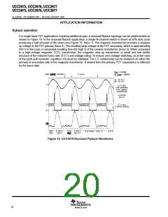
For single layer PZT applications requiring additional gain, a resonant flyback topology can be implemented as
shown in Figure 16. In the resonant flyback application, a single N-channel switch is driven at 50% duty cycle
producing a half sinusoid at the drain (see Figure 16: trace 1). The magnetic transformer provides a stepped
up voltage to the PZT primary (trace 4). The resulting lamp voltage at the PZT secondary, which is approximately
250 V in this case, is sinusoidal resulting from the high Q of the ceramic transformer (trace 3). When compared
to a high-voltage magnetic CCFL transformer, the magnetic step-up transformer is small and low profile
because of the reduced turns ratio (3.5:1) and voltage rating. To ensure zero-voltage switching, as in the case
of the push-pull converter, equation (16) must be validated. The L-C relationship can be analyzed on either the
primary or secondary side of the magnetic transformer. If viewed from the primary, PZT capacitance is reflected
by the turns ratio.
V
V
= 4 Vdc
IN
LAMP
= 250 V
Figure 16. UCC3975 Resonant Flyback Waveforms
20
www.ti.com

 TI [ TEXAS INSTRUMENTS ]