UCC28610
SLUS888C–JANUARY 2009–REVISED SEPTEMBER 2009 ......................................................................................................................................... www.ti.com
Zero Crossing Detection
The modulator requires three conditions in order to initiate the next switching cycle:
1. The time since the last turn-on edge must be equal to or greater than the time that is requested by the
Feedback Processor as determined by the feedback current, IFB
.
2. The time since the last turn-on edge must be longer than the minimum period that is built into the UCC28610
(nominally 7.5 µs which equals 133 kHz).
3. Immediately following a high-to-low zero crossing of the ZCD voltage. Or, it has been longer than tWAIT,ZCD
(~2.4 µs) since the last zero crossing has been detected.
Every switching cycle is preceded by at least one zero crossing detection by the ZCD pin. The modulator allows
the resonant ring to damp between pulses if the period needs to exceed the damping limit, allowing long pauses
between pulses during no-load operation.
The switching frequency is not allowed to exceed 133 kHz (nominally). This sets the maximum power limit so
that it will be constant for all bulk voltages that exceed the minimum line voltage value.
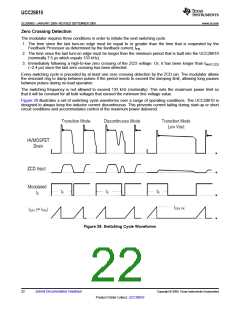
Figure 28 illustrates a set of switching cycle waveforms over a range of operating conditions. The UCC28610 is
designed to always keep the inductor current discontinuous. This prevents current tailing during start-up or short
circuit conditions and accommodates control of the maximum power delivered.
Figure 28. Switching Cycle Waveforms
22
Submit Documentation Feedback
Copyright © 2009, Texas Instruments Incorporated
Product Folder Link(s): UCC28610

 TI [ TEXAS INSTRUMENTS ]