UCC28610
SLUS888C–JANUARY 2009–REVISED SEPTEMBER 2009 ......................................................................................................................................... www.ti.com
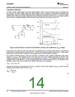
In order to achieve the lowest possible no-load power, select the number of turns in the bias winding so that VDD
is higher than 16 V – VTH of the HVMOSFET. A bias winding voltage between 17 V and 20 V usually achieves
minimum loss. The bias winding often tracks the primary leakage inductance turn-off voltage spike. Place a 20-V
Zener diode between VDD and GND in applications where heavy loads cause excessive VDD voltage.
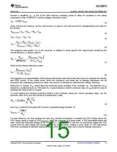
Volts
20
15
VGG
10
VOUT
VDD
5
0
Volts
150
100
50
VBULK
5
10
15
20
25
30
Time (ms)
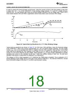
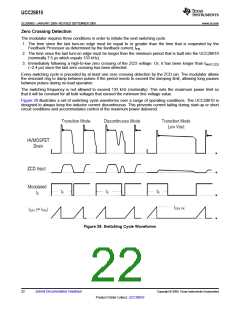
Figure 23. Typical Start-Up Waveforms for a 17-V Bias Winding Voltage
Typical start-up waveforms are shown in Figure 23. As VGG rises, VDD will follow, minus the threshold voltage
of the HVMOSFET. When VDD reaches approximately 10 V, the UCC28610 initiates switching. The bias supply
current, IVDD, rises to its operating level and it is supplied from the VDD capacitor. Start-up times can be kept
under 200 ms by selecting the VGG capacitor in the range of 33 nF to 1000 nF and selecting RSTART to have a
current of 15 µA at the minimum AC line voltage. Select capacitor CVDD to have enough capacitance to provide
operating bias current to the controller for the time it takes the auxiliary winding to take over. No-load burst
operation may impose a requirement for additional CVDD capacitance.
The voltage on VGG is shunt regulated to 16 V whenever the PWM action is disabled. This is reduced to 14 V
during switching to limit voltage stress on the gate of the external HVMOSFET. The external HVMOSFET should
have a threshold voltage of less than 6 V in order to permit proper starting.
18
Submit Documentation Feedback
Copyright © 2009, Texas Instruments Incorporated
Product Folder Link(s): UCC28610

 TI [ TEXAS INSTRUMENTS ]