UCC28610
SLUS888C–JANUARY 2009–REVISED SEPTEMBER 2009 ......................................................................................................................................... www.ti.com
Modulation Modes
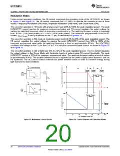
Under normal operating conditions, the FB current commands the operating mode of the UCC28610, as shown
in Figure 25 and Figure 26. The FB current commands the UCC28610 to operate the converter in one of three
modes: Frequency Modulation (FM) mode, Amplitude Modulation (AM) mode, and Green Mode (GM).
The converter operates in FM mode with a large power load (23% to 100% the peak regulated power). The peak
HVMOSFET current reaches its maximum programmed value and FB current regulates the output voltage by
varying the switching frequency, which is inversely proportional to tS. The switching frequency range is nominally
from 30 kHz (23% peak power) to 133 kHz (100% peak power). The maximum programmable HVMOSFET
current, IDRV,PK(max), is set by a resistor on the CL pin, as described in Equation 10.
The converter operates in AM mode at moderate power levels (2.5% to 23% of the peak regulated power). The
FB current regulates the output voltage by varying the peak HVMOSFET current from 33% to 100% of the
maximum programmed value while the switching frequency is fixed at approximately 30 kHz. The UCC28610
modulates the voltage on the CL pin from 3 V to 1 V to vary the commanded peak current, as shown in Figure 25
and Figure 26.
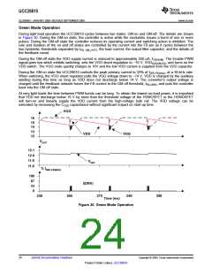
The converter operates in GM at light load (0% to 2.5% of the peak regulated power). The FB current regulates
the output voltage in the Green Mode with hysteretic bursts of pulses using FB current thresholds. The peak
HVMOSFET current is 33% of the maximum programmed value. The switching frequency within a burst of pulses
is approximately 30 kHz. The duration between bursts is regulated by the power supply control dynamics and the
FB hysteresis. The UCC28610 reduces internal bias power between bursts in order to conserve energy during
light-load and no-load conditions.
IFB
Current Modulator
AM
GM
FM
IFB,CNR1
(165uA)
IFB,CNR2
(210uA)
IFB,CNR3
(275uA)
100
Peak
3
Current
Control
IFB,CNR3 - IFB,CNR2
(65uA)
RCL
IFB
33
Freq. Modulator
1/tS
TS W
VGATE
IFB
133
IFB,CNR2 - IFB,CNR1
(45uA)
IGM,HYST
(20uA)
30
0
150
IFB - Feedback Current - µA
300
50
100
200
250
Figure 25. Modulation Control Blocks
Figure 26. Control Diagram with Operating Modes
20
Submit Documentation Feedback
Copyright © 2009, Texas Instruments Incorporated
Product Folder Link(s): UCC28610

 TI [ TEXAS INSTRUMENTS ]