UCC28610
SLUS888C–JANUARY 2009–REVISED SEPTEMBER 2009 ......................................................................................................................................... www.ti.com
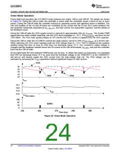
Green Mode Operation
During light load operation the UCC28610 cycles between two states: GM-on and GM-off. The details are shown
in Figure 30. During the GM-on state, the controller is active while the modulator issues a burst of one or more
pulses. During the GM-off state the controller reduces its operating current and switching action is inhibited. The
rate and duration of the on and off states are controlled by the current into the FB pin as it cycles between the
two hysteretic thresholds separated by IFB, GM_HYST, the load current, the output filter capacitor, and the details of
the feedback circuit.
During the GM-off state the VDD supply current is reduced to approximately 550 µA, IVDD(GM). The Enable PWM
signal goes low which inhibits switching, sets the VGG shunt regulation to ~16 V, VGG(DISABLED), and turns on the
VDD switch. The VGG node quickly charges to 16V and the low VDD current is supplied from the VDD capacitor.
During the GM-on state the UCC28610 controls the peak primary current to 33% of IDRV,PK(max), at a 30-kHz rate.
When switching, the VGG shunt regulator pulls the VGG voltage down to ~14 V. VDD is charged by the auxiliary
winding during this time as long as VDD does not discharge below 14 V. The converter’s output voltage is
charged until the feedback network forces the FB current to the GM off threshold, IFB,CNR3, and puts the controller
back into the GM off state.
At very light loads the time between PWM bursts can be long. To obtain the lowest no-load power, it is important
that VDD not discharge below 16 V by more than the threshold voltage of the HVMOSFET or the HVMOSFET
will turn-on and linearly supply the VDD current from the high-voltage bulk rail. The VDD voltage can be
extended by increasing the CVDD capacitance without significant impact on start-up time.
VGG
16
15
14
13
VDD
VGG
12
VOUT
12.1
12.0
11.9
11.8
VOUT
% IDRV, PK(MAX)
100
67
33
0
I(DRV)
250
260
270
280
290
Time (ms)
Figure 30. Green Mode Operation
24
Submit Documentation Feedback
Copyright © 2009, Texas Instruments Incorporated
Product Folder Link(s): UCC28610

 TI [ TEXAS INSTRUMENTS ]