UCC28610
SLUS888C–JANUARY 2009–REVISED SEPTEMBER 2009 ......................................................................................................................................... www.ti.com
Fault Recovery
The UCC28610 reacts with the programmed overload response if the overload lasts longer than tOL (nominally
250 ms). The overload fault responses are either (1) latch-off or (2) shutdown/retry after a retry delay of 750 ms.
The overload response is programmed with the MOT pin. The forced DCM feature prevents transformer
saturation and limits the average and RMS output currents of the secondary winding of the transformer. Even
under short circuit load conditions, the output current of the transformer is limited to the levels that are shown in
Equation 13, where NPS is the primary-to-secondary turns ratio. Typical behavior for a shorted load is shown in
Figure 32.
N
PS ´IDRV ( PEAK )
ISECONDARY ,AVG
=
SHORTEDLOAD
(
)
2
N
PS ´IDRV ( PEAK )
ISECONDARY ,RMS
=
SHORTEDLOAD
(
)
3
(13)
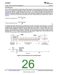
In shutdown/retry mode switching will be re-enabled after the 750-ms retry delay. In latch-off mode, a 7.5-kΩ load
is activated at the DRV pin upon the activation by a fault condition. The internal 7.5-kΩ load draws current from
the bulk capacitor through the HVMOSFET and the transformer primary winding. The bias voltage, VDD, is also
regulated by the HVMOSFET during the latch-off state. Once the AC line is removed, a 2.8-mA current,
IDRV,DSCH, will discharge the bulk capacitor. Ultimately, VDD will discharge when the bulk voltage becomes
sufficiently low. A normal start-up cycle can occur if the input voltage is applied after VDD falls below the fault
reset level, VDD(FAULT RESET), which is approximately equal to 6 V.
tOL = 250ms
50
300
Figure 32. Overload Behavior with a Shorted Output
26
Submit Documentation Feedback
Copyright © 2009, Texas Instruments Incorporated
Product Folder Link(s): UCC28610

 TI [ TEXAS INSTRUMENTS ]