UCC28610
www.ti.com ......................................................................................................................................... SLUS888C–JANUARY 2009–REVISED SEPTEMBER 2009
Maximum Power Limit
The suggested peak power range of the UCC28610 is 12 W to 65 W based on a universal AC line converter
(90-VAC to 265-VAC input line voltage), using an external high voltage MOSFET with a voltage rating of 600 V.
This power range may depend on application and external MOSFET stress voltage. Ultimately, the peak primary
current is the limiting factor because this current must pass through the UCC28610. The limit on the peak
primary current imposes a limit on the peak primary power. The peak power must be less than 65 W, not the
average power. The peak power is defined as the highest power level where the controller must maintain
regulation.
At all power levels, program the UCC28610 to control the power limit with the primary inductance, peak current
and maximum switching frequency (133 kHz). The peak programmed power level is given by Equation 7. The
accuracy of the power limit is twice as sensitive to IDRV(PK) errors than LM errors and fS(max) errors. If the load
demands more power than the programmed level, the power supply output voltage sags and the overload timer
is initiated.
Minimum Power Limit
The dynamics of the DRV current sense imposes the 12-W minimum power level limit for this controller. The
power level limits are found from DRV current estimates for typical universal AC adapters that use a 600-V
MOSFET. The power range and its associated peak current range are given in Equation 12.
P ³ 12W
IN
I
³ 1A
DRV ,PK (min)
(12)
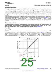
The minimum power level is due to a loss of linearity of the current mirror, as shown in Figure 31. A programmed
IDRV,PK level between 0.66 A and 1 A (by using 100 kΩ ≤ RCL ≤ 150 kΩ) allows only a 2:1 amplitude modulation
range of the peak DRV current. The amplitude of IDRV modulates linearly if IDRV,PK is programmed within its
recommended operating range (1.0 A < IDRV,PK < 4.1 A, corresponding to 100 kΩ > RCL > 24.3 kΩ respectively.
5
Best Results
24.3 kW < R < 100 kW
CL
4
3
2
1
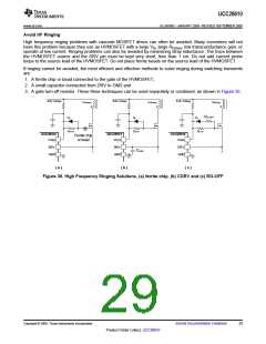
Avoid Operation Here
0
0
10
20
30
40
50
1/R – mS
CL
Figure 31. Dynamic Operating Range
Copyright © 2009, Texas Instruments Incorporated
Submit Documentation Feedback
25
Product Folder Link(s): UCC28610

 TI [ TEXAS INSTRUMENTS ]