UCC28610
www.ti.com ......................................................................................................................................... SLUS888C–JANUARY 2009–REVISED SEPTEMBER 2009
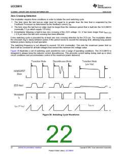
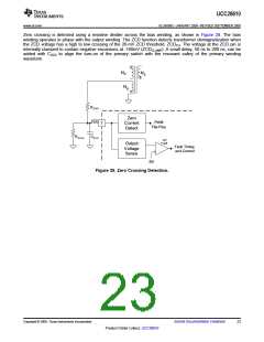
Zero crossing is detected using a resistive divider across the bias winding, as shown in Figure 29. The bias
winding operates in phase with the output winding. The ZCD function detects transformer demagnetization when
the ZCD voltage has a high to low crossing of the 20-mV ZCD threshold, ZCDTH. The voltage at the ZCD pin is
internally clamped to contain negative excursions at -160mV (ZCDCLAMP). A small delay, 50 ns to 200 ns, can be
added with CZCD to align the turn-on of the primary switch with the resonant valley of the primary winding
waveform.
NP
NS
NB
RZCD1
ZCD
Zero
Current
Detect
PWM
Flip-Flop
2
RZCD2
CZCD
OV
Fault
Output
Voltage
Sense
Fault Timing
and Control
5V
Figure 29. Zero Crossing Detection.
Copyright © 2009, Texas Instruments Incorporated
Submit Documentation Feedback
23
Product Folder Link(s): UCC28610

 TI [ TEXAS INSTRUMENTS ]