UCC28951
www.ti.com.cn
ZHCSIQ7A –AUGUST 2018 –REVISED DECEMBER 2021
pullup current taken into account. The latch-off mode can be reset externally if the soft-start capacitor is forcibly
discharged below 0.55 V or the VDD voltage is lowered below the UVLO threshold.
7.3.15 Synchronization (SYNC)
The UCC28951 allows flexible configuration of converters operating in synchronized mode by connecting all
SYNC pins together and by configuration of the controllers as leader and/or followers. The controller configured
as leader (resistor between RT and VREF) provides synchronization pulses at the SYNC pin with the frequency
equal to 2X the converter frequency FSW(nom) and 0.5 duty cycle. The controller configured as a follower (resistor
between RT and GND and 825-kΩresistor between SS_EN pin to GND) does not generate the synchronization
pulses. The follower controller synchronizes its own clock to the falling edge of the synchronization signal thus
operating 90° phase shifted versus the leader converter’s frequency FSW(nom)
.
The output inductor in a full bridge converter sees a switching frequency which is twice that seen by the
transformer. In the case of the UCC28951 this means that the output inductor operates at 2 × FSW(nom). This
means that the 90° phase shift between leader and follower controllers gives a 180° phase shift between the
currents in the output inductors and hence maximum ripple cancellation. For more information about
synchronizing more than two UCC28951 devices, see Synchronizing Three or More UCC28950 Phase-Shifted,
Full-Bridge Controllers (SLUA609).
If the synchronization feature is not used then the SYNC pin may be left floating, but connecting the SYNC pin to
GND through a 10-kΩ resistor will reduce noise pickup and switching frequency jitter.
• If any converter is configured as a follower, the SYNC frequency must be greater than or equal to 1.8 times
the converter frequency.
• follower converter does not start until at least one synchronization pulse has been received.
• If any or all converters are configured as followers, then each converter operates at its own frequency without
synchronization after receiving at least one synchronization pulse. Thus, If there is an interruption of
synchronization pulses at the follower converter, then the controller uses its own internal clock pulses to
maintain operation based on the RT value that is connected to GND in the follower converter.
• In leader mode, SYNC pulses start after SS pin passes its enable threshold which is 0.55 V.
• follower starts generating SS/EN voltage even though synchronization pulses have not been received.
• TI recommends that the SS on the leader controller starts before the SS on the follower controller; therefore
SS/EN pin on leader converter must reach its enable threshold voltage before SS/EN on the follower
converter starts for proper operation. On the same note, TI also recommends that the TMIN resistors on both
leader and follower are set at the same value.
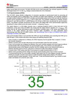
CLK
SYNC_OUT
A
B
图7-16. SYNC_OUT (leader Mode) Timing Diagram
Copyright © 2023 Texas Instruments Incorporated
Submit Document Feedback
35
Product Folder Links: UCC28951
English Data Sheet: SLUSDB2

 TI [ TEXAS INSTRUMENTS ]