TUSB1310A
SLLSE32D–NOVEMBER 2010–REVISED MAY 2011
www.ti.com
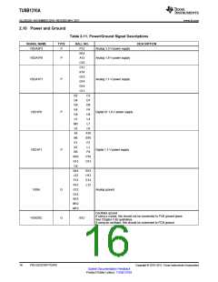
2.10 Power and Ground
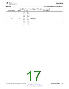
Table 2-11. Power/Ground Signal Descriptions
SIGNAL NAME
TYPE
BALL NO.
P12
DESCRIPTION
VDDA3P3
P
Analog 3.3-V power supply
Analog 1.8-V power supply
N14
VDDA1P8
P
A13
C10
C12
K14
G13
VDDA1P1
P
Analog 1.1-V power supply
G14
D14
C11
B2
C3
D7
D9
F4
D4
D8
E4
VDD1P8
P
Digital IO 1.8-V power supply
G4
H4
L4
L5
M3
L8
L7
L9
A5
A10
B10
F2
B6
E1
K2
L1
VDD1P1
P
Digital 1.1-V power supply
N5
P4
N10
K13
C4
P10
D13
B14
J13
F13
K12
G12
D12
N13
M12
M13
B13
H13
E13
L12
VSSA
G
G
Analog ground
Oscillator ground
If using a crystal, this should not be connected to PCB ground plane.
See Chapter 5 for guidelines.
VSSOSC
B12
If using an oscillator, this should be connected to PCB ground.
16
PIN DESCRIPTIONS
Copyright © 2010–2011, Texas Instruments Incorporated
Submit Documentation Feedback
Product Folder Link(s): TUSB1310A

 TI [ TEXAS INSTRUMENTS ]