TUSB1310A
www.ti.com
SLLSE32D–NOVEMBER 2010–REVISED MAY 2011
Power Supplies
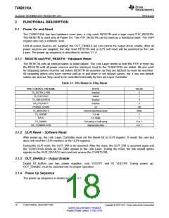
XI
RESETN
Internal latched
strapping pin states
Latched data
Internal resetn/
PLL_EN/SUSPENDM
PCLK
ULPI_CLK
PHY_STATUS/
ULPI_DIR
300 µs
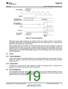
Figure 3-1. Power-Up Sequence
After proper power supply sequencing, the reference clock on XI starts to operate. On the RESETN
deassertion, REFCLKSEL1-0 is determined depending on the PHY_MODE pins, PLL is locked and the
valid ULPI_CLK and the valid PCLK are driven.
After all stable clocks are provided, the TUSB1310A allows the Link Layer Controller to access by
deasserting the ULPI_DIR. The Link Layer Controller sets the Reset bit in the ULPI register. At the PIPE
interface, the PHY_STATUS changes from high to low in order to indicate the TUSB1310A is in the power
state specified by the POWER_DOWN signal. After the PHY_STATUS change, the TUSB1310A is ready
for PIPE transactions.
3.2 Clocks
3.2.1 Clock Distribution
A source clock should be provided via XI/XO from an external crystal or from a square wave clock. The
USB3.0 PLL provides a clock to the PIPE which drives 250 MHz. The USB2.0 PLL provides a 60-MHz
clock to the ULPI.
3.2.2 Output Clock
The CLKOUT is used by the Link Layer Controller or the MAC in low power mode. A 120-MHz clock is
available on the CLKOUT pin only in the USB U3 power state.
3.3 Power Management
The SuperSpeed USB power state transition is controlled by the PIPE POWER_DOWN[1-0] and the
Non-SuperSpeed USB power state is transitioned by setting suspendM bit in the ULPI Function control
register via the ULPI or by asserting the ULPI_STP.
Copyright © 2010–2011, Texas Instruments Incorporated
FUNCTIONAL DESCRIPTION
19
Submit Documentation Feedback
Product Folder Link(s): TUSB1310A

 TI [ TEXAS INSTRUMENTS ]