TUSB1310A
SLLSE32D–NOVEMBER 2010–REVISED MAY 2011
www.ti.com
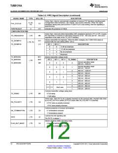
Table 2-2. PIPE Signal Description (continued)
SIGNAL NAME
TYPE
BALL NO.
DESCRIPTION
Active High. Used to communicate completion of several PHY functions including power
management state transitions, rate change, and receiver detection. When this signal
transitions during entry and exit from P3 and PCLK is not running, then the signaling is
asynchronous.
S, I/O,
PD
PHY_STATUS
E3
PWRPRESENT
O
H11
Indicates the presence of VBUS
CONFIGURATION PINS
Active High. Used only when transmitting USB compliance pat-terns CP7 or CP8. Causes
the transmitter to transmit an alternating sequence of 50 - 250 ones and 50 - 250 zeros –
regardless of the state of the TX_DATA interface.
TX_ONESZEROS
I, PD
M4
Selects transmitter de-emphasis. When the MAC changes, the TUSB1310A starts to
transmit with the new setting within 128 ns.
TX_DEEMPH1
K11
L11
I, PD, PU
TX_DEEMPH0
BIT 1
BIT 0
DESCRIPTION
0
0
1
1
0
1
0
1
-6 dB de-emphasis
-3.5 dB de-emphasis
No de-emphasis
Reserved
TX_MARGIN2
TX_MARGIN1
M11
M10
Selects transmitter voltage levels
BIT 2
BIT 1
BIT 0
TX_SWING
DESCRIPTION
I, PD
Normal operating range
800 mV - 1200 mV
TX_MARGIN0
M9
0
0
0
0
Normal operating range
400 mV - 700 mV
0
0
0
0
0
1
1
0
1
0
1
0
1
0
1
800 mV - 1200 mV
400 mV - 700 mV
700 mV - 900 mV
300 mV - 500 mV
400 mV - 600 mV
200 mV - 400 mV
200 mV - 400 mV
100 mV - 200 mV
0
0
1
1
0
1
1
1
Don't care
Controls transmitter voltage swing level
0 Full swing
TX_SWING
I, PD
I, PD
M5
C8
1 Half swing
Active High. Tells PHY to do a polarity inversion on the received data. Inverted data show
up on RX_DATA15-0 within 20 PCLK clocks after RX_POLARITY is asserted.
RX_POLARITY
0 PHY does no polarity inversion.
1 PHY does polarity inversion.
Controls presence of receiver terminations
0 Terminations removed
RX_TERMINATION
RATE
I, PD
I, PU
I, PD
D3
L6
C9
1 Terminations present
Controls the link signaling rate
The RATE is always 1.
Selects elasticity buffer operating mode
0 Nominal half full buffer mode
1 Nominal empty buffer mode
ELAS_BUF_MODE
12
PIN DESCRIPTIONS
Copyright © 2010–2011, Texas Instruments Incorporated
Submit Documentation Feedback
Product Folder Link(s): TUSB1310A

 TI [ TEXAS INSTRUMENTS ]