TUSB1310A
www.ti.com
SLLSE32D–NOVEMBER 2010–REVISED MAY 2011
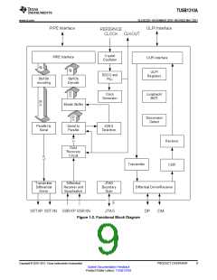
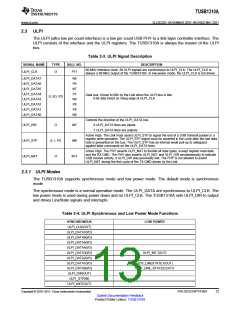
2.3 ULPI
The ULPI (ultra low pin count interface) is a low pin count USB PHY to a link layer controller interface. The
ULPI consists of the interface and the ULPI registers. The TUSB1310A is always the master of the ULPI
bus.
Table 2-3. ULPI Signal Description
SIGNAL NAME
TYPE
BALL NO.
DESCRIPTION
60-MHz interface clock. All ULPI signals are synchronous to ULPI_CLK. The ULPI_CLK is
always a 60-MHz output of the TUSB1310A. In low power mode, the ULPI_CLK is not driven.
ULPI_CLK
O
P11
ULPI_DATA7
ULPI_DATA6
ULPI_DATA5
ULPI_DATA4
ULPI_DATA3
ULPI_DATA2
ULPI_DATA1
ULPI_DATA0
N6
P6
N7
P7
N8
P8
P9
N9
Data bus. Driven to 00h by the Link when the ULPI bus is idle.
8-bit data timed on rising edge of ULPI_CLK
S, I/O, PD
Controls the direction of the ULPI_DATA bus
0 ULPI_DATA lines are inputs
ULPI_DIR
ULPI_STP
ULPI_NXT
O
S, I, PU
O
M7
M8
1 ULPI_DATA lines are outputs
Active High. The Link must assert ULPI_STP to signal the end of a USB transmit packet or a
register write operation. The ULPI_STP signal must be asserted in the cycle after the last data
byte is presented on the bus. The ULPI_STP has an internal weak pull-up to safeguard
against false commands on the ULPI_DATA lines.
Active High. The PHY asserts ULPI_NXT to throttle all data types, except register read data
and the RX CMD. The PHY also asserts ULPI_NXT and ULPI_DIR simultaneously to indicate
USB receive activity, if ULPI_DIR was previously low. The PHY is not allowed to assert
ULPI_NXT during the first cycle of the TX CMD driven by the Link.
N11
2.3.1 ULPI Modes
The TUSB1310A supports synchronous mode and low power mode. The default mode is synchronous
mode.
The synchronous mode is a normal operation mode. The ULPI_DATA are synchronous to ULPI_CLK. The
low power mode is used during power down and no ULPI_CLK. The TUSB1310A sets ULPI_DIR to output
and drives LineState signals and interrupts.
Table 2-4. ULPI Synchronous and Low Power Mode Functions
SYNCHRONOUS
ULPI_CLK(OUT)
ULPI_DATA7(I/O)
ULPI_DATA6(I/O)
ULPI_DATA5(I/O)
ULPI_DATA4(I/O)
ULPI_DATA3(I/O)
ULPI_DATA2(I/O)
ULPI_DATA1(I/O)
ULPI_DATA0(I/O)
ULPI_DIR(OUT)
ULPI_STP(IN)
LOW POWER
ULPI_INT (OUT)
ULPI_LINESTATE1(OUT)
ULPI_LINE_STATE0 (OUT)
ULPI_NXT(OUT)
Copyright © 2010–2011, Texas Instruments Incorporated
PIN DESCRIPTIONS
13
Submit Documentation Feedback
Product Folder Link(s): TUSB1310A

 TI [ TEXAS INSTRUMENTS ]