TUSB1310A
www.ti.com
SLLSE32D–NOVEMBER 2010–REVISED MAY 2011
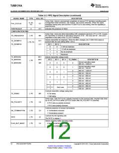
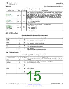
Table 2-8. Strapping Options (continued)
SIGNAL NAME
TYPE
BALL NO.
DESCRIPTION
Active High. Puts PIPE into isolate mode. When in the isolate mode, TUSB1310A does
not respond to packet data present at TX_DATA15-0, TXDATAK1-0 inputs and presents
a high impedance on the PCLK, RX_DATA15-0, RX_DATAK1-0, RX_VALID outputs.
When in the isolate mode, the TUSB1310A will continue to respond to ULPI. Once the
isolate mode bit in ULPI register is cleared, the USB interfaces will start transmitting
packet data on TX_DATA15-0 and driving PCLK, RX_DATA15-0, RX_DATA1-0, and
RX_VALID.
ISO_START
(ULPI_DATA7)
S, I/O, PD
N6
Selects ULPI data bus bit width
ULPI_8BIT
(ULPI_DATA6)
S, I/O, PD
S, I/O, PD
P6
0
8-bit ULPI SDR mode
Must be set to 0.
Select input reference clock frequency for on-chip oscillator
00 20 MHz on XI
REFCLKSEL1,
REFCLKSEL0
(ULPI_DATA5,
ULPI_DATA4)
N7
P7
01 25 MHz on XI
10 30 MHz on XI
11 40 MHz on XI
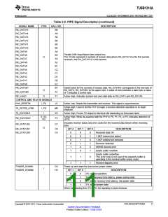
2.8 USB Interfaces
Table 2-9. USB Interface Signal Name Descriptions
SIGNAL NAME
SSTXP
TYPE
BALL NO.
H14
DESCRIPTION
USB SuperSpeed transmitter differential pair
O
SSTXM
SSRXP
SSRXM
DP
J14
E14
I
USB SuperSpeed receiver differential pair
USB non-SuperSpeed differential pair
F14
P14
I/O
I
DM
P13
USB VBUS pin
Connected through an external voltage divider.
VBUS
N12
2.9 Special Connect
Table 2-10. Special Connect Signal Descriptions
SIGNAL NAME
R1EXT
TYPE
BALL NO.
DESCRIPTION
High precision external resistor used for calibration. The R1 value shall be 10 kΩ ±1%
O
L14
accuracy.
R1EXTRTN
VDDA1P1
I
L13
M14
D6
R1 ground reference. This pin is not connected to board ground.
P
Needs a 1-µF bypass capacitor
D5
C13
C14
K4
RSVD
I/O
Must be left open.
J4
A14
Copyright © 2010–2011, Texas Instruments Incorporated
PIN DESCRIPTIONS
Submit Documentation Feedback
15
Product Folder Link(s): TUSB1310A

 TI [ TEXAS INSTRUMENTS ]