TUSB1310A
SLLSE32D–NOVEMBER 2010–REVISED MAY 2011
www.ti.com
3.3.1 USB Power Management
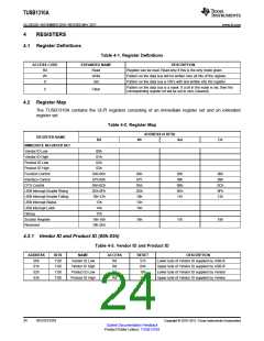
The USB 3.0 specification improves power consumption by defining 4 power states, U0, U1, U2, and U3
while the PIPE specification defines P0, P1, P2 and P3. The POWER_DOWN pin states are mapped to
LTSSM states as described in Table 3-2. For all power state transitions, the Link Layer Controller must not
begin any operational sequences or further power state transitions until the TUSB1310A has indicated that
the internal state transition is completed.
Table 3-2. Power States
PIPE
POWER
STATE
USB POWER STATE
PCLK
PLL
TRANSMITTING
RECEIVING
PHY_STATUS
U0, all other LTSSM
states
P0
P1
P2
On
On
On
On
On
On
Active or Idle or LFPS
Idle or LFPS
Active or Idle
A single cycle assertion
A single cycle assertion
A single cycle assertion
U1
Idle
Idle
U2, RxDetect,
SS.Inactive
Idle or LFPS or
RxDetect
PHY_STATUS is
asserted before PCLK is
turned off and
de-asserted when PCLK
is fully off.
Off. The PIPE is in
an asynchronous
mode
P3
U3, SS.disabled
Off
LFPS or RxDetect
Idle
When the Link Layer Controller wants to transmit LFPS in P1, P2, or P3 state, it must de-assert
TX_ELECIDLE. The TUSB1310A generates valid LFPS until the TX_ELECIDLE is asserted. The Link
Layer Controller must assert TX_ELECIDLE before transitioning to P0.
When RX_ELECIDLE is de-asserted in P0, P1, P2, or P3, the TUSB1310A receiver monitors for LFPS
except during reset or when RX_TERMINATION is removed for electrical idle.
When the TUSB1310A is in P0 and is actively transmitting; only RX_POLARITY can be asserted.
Table 3-3. PIPE Control Pin Matrix
POWER STATE
TX_DETRX_LPBK
TX_ELECIDLE
DESCRIPTION
Transmitting data on TX_DATA.
Not transmitting and is in electrical idle
Goes into loopback mode
0
0
1
1
0
1
0
1
0
1
0
1
1
0
1
P0
Transmits LFPS signaling
Transmits LFPS signaling
P1
P2
P3
Don’t care
Not transmitting and is in electrical idle
Transmits LFPS signaling
Don’t care
0
1
Idle
Does a receiver detection operation
Transmits LFPS signaling
Don’t care
Does a receiver detection operation
20
FUNCTIONAL DESCRIPTION
Copyright © 2010–2011, Texas Instruments Incorporated
Submit Documentation Feedback
Product Folder Link(s): TUSB1310A

 TI [ TEXAS INSTRUMENTS ]