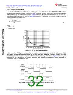
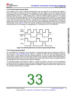
TPS7H5005-SEP, TPS7H5006-SEP, TPS7H5007-SEP, TPS7H5008-SEP
www.ti.com
SLVSGG1 – FEBRUARY 2022
VOUT
RTOP1
VSENSE
VSENSE
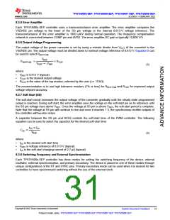
RT
RT
RBOTTOM1
COMP
COMP
RCOMP1
CHF1
CCOMP1
TPS7H500x-SEP
(Primary)
SS
SYNC
SS
CSS1
HICC
HICC
CHICC1
VSENSE
COMP
VSENSE
COMP
RT
TPS7H500x-SEP
(Secondary)
SYNC
SS
SS
HICC
HICC
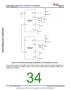
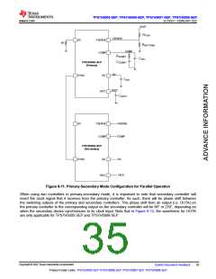
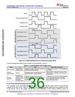
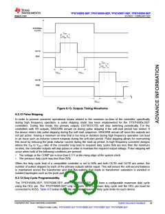
Figure 8-11. Primary-Secondary Mode Configuration for Parallel Operation
When using two controllers in primary-secondary mode, it is important to note that secondary controller will
invert the clock signal that it receives from the primary controller. As such, there will be phase shift between
the switching outputs of the primary and secondary controllers. This phase shift from an output (i.e. OUTA) on
the primary controller to the corresponding output on the secondary controller will be 90° or 270°, depending on
when the secondary device synchronizes to its clock input. Note that in Figure 8-12, the waveforms for OUTB
are only applicable for TPS7H5005-SEP and TPS7H5008-SEP.
Copyright © 2022 Texas Instruments Incorporated
Submit Document Feedback
35
Product Folder Links: TPS7H5005-SEP TPS7H5006-SEP TPS7H5007-SEP TPS7H5008-SEP

 TI [ TEXAS INSTRUMENTS ]