TPS65163
SLVSA28 –OCTOBER 2009
www.ti.com
PROTECTION (BUCK CONVERTER)
To protect against short-circuit conditions, the buck converter automatically limits its output current when the
voltage applied to its FBB pin is less than 1.065 V. To reduce power dissipation in the IC, the buck converter
switches at 25% of its nominal switching frequency as long as VFBB < 1.065 V. When VFBB is between 1.065 V
and 2.13 V, the buck converter switches at 50% of its nominal switching frequency.
Note: Because the negative charge pump is driven from its switch node, a short-circuit condition on the buck
converter output also causes the loss of VGL until the short circuit is removed.
An internal pullup prevents the buck converter from generating excessive output voltages if its FBB pin is left
floating.
Buck Converter Design Procedure
Because the negative charge pump is driven from the buck converter switch node, the effective output current for
design purposes is greater than ILOGIC alone. For best performance, the effective current calculated using
Equation 11 should be used during the design.
VGL ´ IGL
ILOGIC(EFFECTIVE) = I
+
LOGIC
VLOGIC
(11)
Calculate Converter Duty Cycle (Buck Converter)
The simplest way to calculate the converter duty cycle is to use the efficiency curve in Figure 7 to determine the
converter efficiency under the anticipated load conditions and insert this value into Equation 12 (1). Alternatively,
a worst-case value (e.g., 80%) can be used for efficiency.
VLOGIC
D =
V
´ η
IN
(12)
(1) Valid only when buck converter operates in CCM.
Calculate Maximum Output Current (Buck Converter)
The maximum output current that the buck converter can supply can be calculated using Equation 13. The
minimum specified output current occurs at the minimum duty cycle (which occurs at maximum VIN) and
maximum frequency (900 kHz).
V
´ (1 - D)
2 ´ ¦SW ´ L
IN
ILOGIC(EFFECTIVE) = ISW(LIM)
-
´ D
(13)
Where ISW(LIM) is the minimum specified switch current limit (1.5 A) and ƒSW is the converter switching frequency.
Calculate Peak Switch Current (Buck Converter)
Equation 14 can be used to calculate the peak switch current occurring in a given application. The worst-case
(maximum) peak current occurs at maximum VIN.
V
´ (1 - D)
2 ´ ¦SW ´ L
IN
ISW(PK) = ILOGIC(EFFECTIVE)
+
´ D
(14)
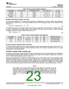
Inductor Selection (Buck Converter)
The buck converter is designed for use with inductors in the range 6.8 µH to 15 µH, and is optimized for 10 µH.
The inductor must be capable of supporting the peak current calculated by Equation 14 without saturating.
Alternatively, a more conservative approach can be used in which an inductor is selected whose saturation
current is greater than the maximum switch current limit (2.25 A).
Another important parameter is dc resistance, which can significantly affect the overall converter efficiency.
Physically larger inductors tend to have lower dc resistance (DCR) due to the use of thicker wire. The type and
core material of the inductor can also affect efficiency, sometimes by as much as 10%. Table 4 shows some
suitable inductors.
22
Submit Documentation Feedback
Copyright © 2009, Texas Instruments Incorporated
Product Folder Link(s) :TPS65163

 TI [ TEXAS INSTRUMENTS ]