TPS65163
SLVSA28 –OCTOBER 2009
www.ti.com
Calculate Peak Switch Current (Boost Converter)
Equation 4 can be used to calculate the peak switch current occurring in a given application. The worst-case
(maximum) peak current occurs at the minimum input voltage and maximum duty cycle.
I
V
´ D
S
IN
I
=
+
1 - D 2 ´ ¦
SW(PK)
´ L
SW
(4)
Inductor Selection (Boost Converter)
The boost converter is designed for use with inductors in the range 6.8 µH to 15 µH. A 10-µH inductor is typical.
Inductors should be capable of supporting at least 125% of the peak current calculated by Equation 4 without
saturating. This ensures sufficient margin to tolerate heavy load transients. Alternatively, a more conservative
approach can be used in which an inductor is selected whose saturation current is greater than the maximum
switch current limit (4.2 A).
Another important parameter is dc resistance, which can significantly affect the overall converter efficiency.
Physically larger inductors tend to have lower dc resistance (DCR) because they can use thicker wire. The type
and core material of the inductor can also affect efficiency, sometimes by as much as 10%. Table 1 shows some
suitable inductors.
Table 1. Boost Converter Inductor Selection
PART NUMBER
CDRH8D43
INDUCTOR VALUE
10 µH
COMPONENT SUPPLIER
SIZE (L×W×H, mm)
8.3 × 8.3 × 4.5
8.3 × 8.3 × 4
ISAT / DCR
4 A / 29 mΩ
3 A / 38 mΩ
4.8 A / 26 mΩ
4 A / 28 mΩ
Sumida
Sumida
Coilcraft
Wuerth
CDRH8D38
10 µH
MSS 1048-103
744066100
10 µH
10.5 × 10.5 × 5.1
10 × 10 × 3.8
10 µH
Rectifier Diode Selection (Boost Converter)
For highest efficiency, the rectifier diode should be a Schottky type. Its reverse voltage rating should be higher
than the maximum output voltage VS. The average rectified forward current through the diode is the same as the
output current.
ID(AVG) = IS
(5)
A Shottky diode with a 2-A average rectified current rating is adequate for most applications. Smaller diodes can
be used in applications with lower output current; however, the diode must be able to handle the power
dissipated in it, which can be calculated using Equation 6. Table 2 lists some diodes suitable for use in typical
applications.
P
= ID(AVG) ´ VF
D
(6)
Table 2. Boost Converter Rectifier Diode Selection
PART NUMBER
MBRS320
SL22
VR / IAVG
20 V / 3 A
20 V / 2 A
20 V / 2 A
VF
RθJA
SIZE
SMC
SMB
SMB
COMPONENT SUPPLIER
International Rectifier
0.44 V at 3 A
0.44 V at 2 A
0.5 V at 2 A
46°C/W
75°C/W
75°C/W
Vishay Semiconductor
Fairchild Semiconductor
SS22
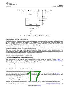
Output Capacitance Selection (Boost Converter)
For best performance, a total output capacitance (COUTA + COUTB in Figure 39) in the range 50 µF to 100 µF is
recommended. At least 20 µF of the total output capacitance should be connected directly to the cathode of the
boost converter rectifier diode, i.e., in front of the isolation switch.
Operating the boost converter with little or no capacitance in front of the isolation switch may cause overvoltage
conditions that reduce reliability of the TPS65163.
Table 3 suggests some output capacitors suitable for use with the boost converter.
18
Submit Documentation Feedback
Copyright © 2009, Texas Instruments Incorporated
Product Folder Link(s) :TPS65163

 TI [ TEXAS INSTRUMENTS ]