TPS54531
SLVSBI5 –MAY 2013
www.ti.com
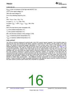
OUTPUT FILTER COMPONENTS
Two components need to be selected for the output filter, LOUT and COUT. Since the TPS54531 is an externally
compensated device, a wide range of filter component types and values can be supported.
Inductor Selection
To calculate the minimum value of the output inductor, use Equation 8
VOUT
´
VIN(MAX) - VOUT
(
)
´ KIND ´IOUT ´FSW
LMIN
=
V
IN(MAX)
(8)
KIND is a coefficient that represents the amount of inductor ripple current relative to the maximum output current.
In general, this value is at the discretion of the designer; however, the following guidelines may be used. For
designs using low ESR output capacitors such as ceramics, a value as high as KIND = 0.3 may be used. When
using higher ESR output capacitors, KIND = 0.2 yields better results.
For this design example, use KIND = 0.3 and the minimum inductor value is calculated to be 4.8 μH. For this
design, a close standard value was chosen: 4.7 μH.
For the output filter inductor, it is important that the RMS current and saturation current ratings not be exceeded.
The RMS inductor current can be found from Equation 9
æ
ç
ç
è
ö2
÷
VOUT
´
V
- VOUT
(
)
IN(MAX)
1
IL(RMS)
=
I2OUT(MAX)
+
´
÷
12
V
´ LOUT ´ FSW ´ 0.8
IN(MAX)
ø
(9)
and the peak inductor current can be determined with Equation 10
VOUT
´
V
- VOUT
(
IN(MAX)
)
IN(MAX)
IL(PK) = IOUT(MAX)
+
1.6 ´ V
´ LOUT ´ FSW
(10)
For this design, the RMS inductor current is 5.03 A and the peak inductor current is 5.96 A. The chosen inductor
is a Wurth 4.7 μH. It has a saturation current rating of 19.0 A and an RMS current rating of 7.0 A, meeting these
requirements. Smaller or larger inductor values can be used depending on the amount of ripple current the
designer wishes to allow so long as the other design requirements are met. Larger value inductors will have
lower ac current and result in lower output voltage ripple, while smaller inductor values will increase ac current
and output voltage ripple. In general, inductor values for use with the TPS54531 are in the range of 1 μH to
47μH.
Capacitor Selection
There are three primary considerations for selecting the value of the output capacitor. The output capacitor
determines the modulator pole, the output voltage ripple, and how the regulator responds to a large change in
load current. The output capacitance needs to be selected based on the more stringent of these three criteria
The desired response to a large change in the load current is the first criteria. The output capacitor needs to
supply the load with current when the regulator can not. This situation would occur if there are desired hold-up
times for the regulator where the output capacitor must hold the output voltage above a certain level for a
specified amount of time after the input power is removed. The regulator is also temporarily not able to supply
sufficient output current if there is a large, fast increase in the current needs of the load such as a transition from
no load to full load. The regulator usually needs two or more clock cycles for the control loop to see the change
in load current and output voltage and adjust the duty cycle to react to the change. The output capacitor must be
sized to supply the extra current to the load until the control loop responds to the load change. The output
capacitance must be large enough to supply the difference in current for 2 clock cycles while only allowing a
tolerable amount of drop in the output voltage. Equation 11 shows the minimum output capacitance necessary to
accomplish this.
2×DIout
Co >
f sw ×DVout
(11)
12
Submit Documentation Feedback
Copyright © 2013, Texas Instruments Incorporated
Product Folder Links: TPS54531

 TI [ TEXAS INSTRUMENTS ]