TPS51640A, TPS59640, TPS59641
SLUSAQ2 –JANUARY 2012
www.ti.com
LOAD
LOAD
VCORE
VCORE
ISUM
COMP
ISUM
COMP
SW_CLK
SW_CLK
Phase 1
Phase 2
Phase 3
Phase 1
Phase 2
Phase 3
Time
UDG-11034
UDG-11033
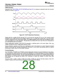
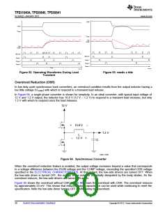
Figure 62. Operating Waveforms During Load
Transient
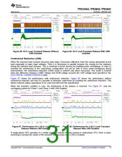
Figure 63. needs a title
Overshoot Reduction (OSR)
In low duty-cycle synchronous buck converters, an overshoot condition results from the output inductor having a
too little voltage (VCORE) with which to respond to a transient load release.
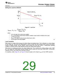
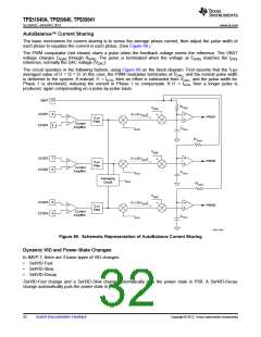
In Figure 64, a single phase converter is shown for simplicity. In an ideal converter, with typical input voltage of
12 V and 1.2-V output, the inductor has 10.8 V (12 V – 1.2 V) to respond to a transient load increase, but only
1.2 V with which to respond once the load releases.
12 V
+
10.8 V
–
1.2 V
L
1.2 V
–
+
C
UDG-11035
Figure 64. Synchronous Converter
When the overshoot reduction feature is enabled, the output voltage increases beyond a value that corresponds
to a voltage difference between the ISUM voltage and the COMP voltage, exceeding the specified OSR voltage
specified in the ELECTRICAL CHARACTERISTICS. At that instant, the low-side drivers are turned OFF. When
the low-side driver is turned OFF, the energy in the inductor is partially dissipated by the body diodes. As the
overshoot reduces, the low-side drivers are turned ON again.
Figure 65 shows the overshoot without OSR. Figure 66 shows the overshoot with OSR. The overshoot reduces
by approximately 23 mV. This shows that reduced output capacitance can be used while continuing to meet the
specification. Note the low-side driver turning OFF briefly during the overshoot.
30
Submit Documentation Feedback
Copyright © 2012, Texas Instruments Incorporated

 TI [ TEXAS INSTRUMENTS ]