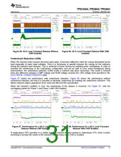
TPS51640A, TPS59640, TPS59641
www.ti.com
SLUSAQ2 –JANUARY 2012
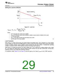
Setting the Load-line (DROOP)
V
VID
Slope of Loadline R
LL
V
V
= R x I
DROOP LL CC
DROOP
I
CC
UDG-11032
Figure 61. Load Line
RCS eff ´ ACS ´ICC
( )
VDROOP = RLL ´ICC
=
RDROOP ´ GM
where
•
•
•
•
•
ACS is the gain of the current sense amplifier
RCS(eff) is the effective current sense resistance, whether a sense resistor or inductor DCR is used
ICC is the load current
RDROOP is the value of resistor from the DROOP pin to VREF
GM is the gain of the droop amplifier
(1)
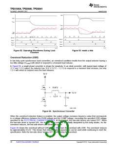
Load Transients
When there is a sudden load increase, the output voltage immediately drops. This is reflected as a rising voltage
on the COMP pin. This forces the PWM pulses to come in sooner and more frequent which causes the inductor
current to rapidly increase. As the inductor current reaches the new load current, a steady-state operating
condition is reached and the PWM switching resumes the steady-state frequency.
When there is a sudden load release, the output voltage rises. This is reflected as a falling voltage on the COMP
pin. This delays the PWM pulses until the inductor current reaches the new load current level. At that point,
switching resumes and steady-state switching continues.
For simplicity, neither Figure 62, nor Figure 63 show the ripple on the Output VCORE nor the COMP waveform.
Copyright © 2012, Texas Instruments Incorporated
Submit Documentation Feedback
29

 TI [ TEXAS INSTRUMENTS ]