TPS51640A, TPS59640, TPS59641
www.ti.com
SLUSAQ2 –JANUARY 2012
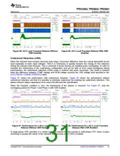
Figure 65. 43-A Load Transient Release Without
Figure 66. 43-A Load Transient Release With OSR
Enabled
OSR Enabled.
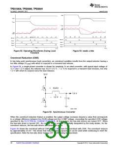
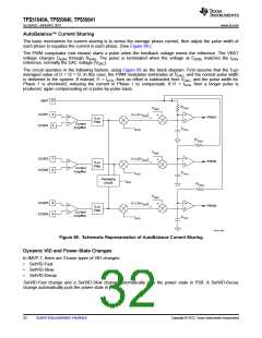
Undershoot Reduction (USR)
When the transient load increase becomes quite large, it becomes difficult to meet the energy demanded by the
load especially at lower input voltages. Then it is necessary to quickly increase the energy tin the inductors
during the transient load increase. This is achieved in these devices by enabling pulse overlapping. In order to
maintain the interleaving of the multi-phase configuration and yet be able to have pulse-overlapping during
load-insertion, the undershoot reduction (USR) mode is entered only when necessary. This mode is entered
when the difference between COMP voltage and ISUM voltage exceeds the USR voltage level specified in the
ELECTRICAL CHARACTERISTICS table.
Figure 67 shows the performance with undershoot reduction. Figure 68 shows the performance without
undershoot reduction and that it is possible to eliminate undershoot by enabling the undershoot reduction. This
allows reduced output capacitance to be used and still meet the specification.
When the transient condition is over, the interleaving of the phases is resumed. For Figure 67, note the
overlapping pulses for Phase 1 and Phase 2 with USR enabled.
Figure 67. Performance for a 43-A Load Transient
Release Without USR Enabled
Figure 68. Performance for a 43-A Load Transient
Release With USR Enabled
A single-phase GPU operates in a similar way, but instead of pulse-overlap in multi-phase CPU, there is pulse
stretching to provide the needs of the transient load increase when USR is enabled.
Copyright © 2012, Texas Instruments Incorporated
Submit Documentation Feedback
31

 TI [ TEXAS INSTRUMENTS ]