TPS51640A, TPS59640, TPS59641
SLUSAQ2 –JANUARY 2012
www.ti.com
PWM Operation
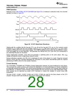
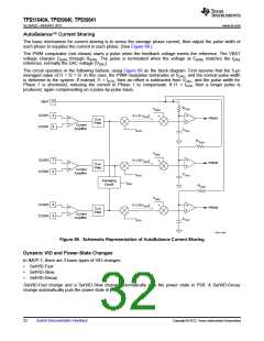
Referring to the FUNCTIONAL BLOCK DIAGRAM and Figure 60, in continuous conduction mode, the converter
operates as shown in Figure 60.
VCORE
ISUM
VCOMP
SW_CLK
Phase 1
Phase 2
Phase 3
Time
UDG-11031
Figure 60. D-CAP+ Mode Basic Waveforms
Starting with the condition that the hig-side FETs are off and the low-side FETs are on, the summed current
feedback (ISUM) is higher than the error amplifier output (VCOMP). ISUM falls until it reaches the VCOMP level, which
contains a component of the output ripple voltage. The PWM comparator senses where the two waveform values
cross and triggers the on-time generator. This generates the internal SW_CLK. Each SW_CLK corresponds to
one switching ON pulse for one phase.
During single-phase operation, every SW_CLK generates a switching pulse on the same phase. Also, ISUM
voltage corresponds to just a single-phase inductor current.
During multi-phase operation, the SW_CLK is distributed to each of the phases in a cycle. Using the summed
inductor current and then cyclically distributing the ON-pulses to each phase automatically yields the required
interleaving of 360/N, where N is the number of phases.
Current Sensing
The TPS51640A, TPS59640 and TPS59641 provide independent channels of current feedback for every phase.
This increases the system accuracy and reduces the dependence of circuit performance on layout compared to
an externally summed architecture. The current sensing topology can be Inductor DCR Sensing, which yields the
best efficiency, or Resistor Current Sensing, which provides the most accuracy across wide temperature range.
DCR sensing can be optimized by using a NTC thermistor to reduce the variation of current sense with
temperature.
The pins CCSP1, CCSN1, CCSP2, CCSN2 and CCSP3, CCSN3 are used for the three phases of the CPU
channel. The pins GCSP and GCSN are used for the single-phase GPU channel.
28
Submit Documentation Feedback
Copyright © 2012, Texas Instruments Incorporated

 TI [ TEXAS INSTRUMENTS ]