TPS51640A, TPS59640, TPS59641
www.ti.com
SLUSAQ2 –JANUARY 2012
User Selections
After the 5-V and the 3.3-V power are applied to the controller, the controller must be enabled by the VR_ON
signal going high to the VCCIO logic level. At this time, the following information is latched and cannot be
changed anytime during operation. The ELECTRICAL CHARACTERISTICS table defines the values of each of
the selections.
•
Operating Frequency. The resistor from CF-IMAX pin to GND sets the frequency of the CPU channel. The
resistor from GF-IMAX to GND sets the frequency of the GPU channel. See the ELECTRICAL
CHARACTERISTICS table for the resistor settings corresponding to each frequency selection. It is to be
noted that the operating frequency is a quasi-fixed frequency in the sense that the ON time is fixed based on
the input voltage (at the VBAT pin) and output voltage (set by VID). The OFF time varies based on various
factors such as load and power-stage components.
•
Maximum Current Limit (ICC(max)) Information. The ICC(max) information of the CPU, which can be set by the
voltage on the CF-IMAX pin. The ICC(max) information of the GPU channel, which can be set by the voltage on
the GF-IMAX pin.
•
•
Overcurrent Protection (OCP) Level. The resistor from COCP-I to GND sets the OCP level of the CPU
channel. The resistor from GOCP-I to GND sets the OCP level of the GPU channel.
Current Monitor (IMON) Gain and Voltage. The resistor from CIMON to COCP-I sets the CIMON gain and
the CIMON voltage for the CPU channel. The resistor from GIMON to GOCP-I sets the GIMON gain and the
GIMON voltage for the GPU channel.
•
•
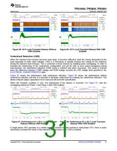
Overshoot Reduction (OSR) and Undershoot Reduction (USR) Levels. The resistor from the CSKIP pin
to GND sets the OSR and USR for the CPU channel. The resistor from the GSKIP pin to GND sets the OSR
and USR level for GPU channel. The OSR can be disabled for CPU and/or GPU by setting a voltage of
approximately 200 mV on the corresponding xSKIP pin. This is accomplished by connecting a resistor from
VREF to the xSKIP pin.
Slew Rate. The SetVID-Fast slew rate is set by the voltage on the SLEWA pin. The rate is the same for both
the CPU and GPU channels. The SetVID-Slow is ¼ of the SetVID-Fast rate.
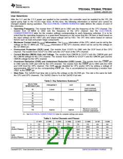
Table 2. Key Selections Summary(1)
SELECTION
RESISTANCE (kΩ)
FREQUENCY
OCP
OSR / USR
Least overshoot,
least undershoot
20
Lowest
Lowest
24
30
39
Rising
Rising
Rising
56
75
100
Maximum overshoot,
maximum undershoot
150
Highest
Highest
(1) See ELECTRICAL CHARACTERISTICS table for complete settings and values.
Table 3. Active Channels and Phases
CCSP1
CS
CCSN1
CS
CCSP2
CS
CCSN2
CS
CCSP3
CS
CCSN3
CS
GCSP
n/a
CGSN
n/a
3
2
CS
CS
CS
CS
3.3 V
GND
GND
n/a
GND
GND
GND
n/a
n/a
n/a
CPU
(Active Phases)
1
CS
CS
3.3 V
GND
n/a
GND
GND
n/a
n/a
n/a
OFF
1
3.3 V
n/a
GND
n/a
n/a
n/a
CS
CS
GPU
(Active Phases)
OFF
n/a
n/a
n/a
n/a
n/a
n/a
3.3 V
GND
Copyright © 2012, Texas Instruments Incorporated
Submit Documentation Feedback
27

 TI [ TEXAS INSTRUMENTS ]