TPS40210-Q1, TPS40211-Q1
SLVS861D –AUGUST 2008–REVISED APRIL 2010
www.ti.com
V
IN
I
OUT
TPS40210/11
RC VDD 10
L
1
2
3
4
5
SS
BP
GDRV
ISNS
9
8
7
6
DIS/EN
COMP
FB
R
IFB
GND
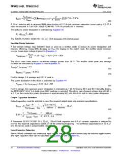
UDG-07197
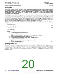
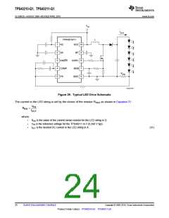
Figure 29. Typical LED Drive Schematic
The current in the LED string is set by the choice of the resistor RISNS as shown in Equation 31.
V
FB
R
=
IFB
I
OUT
where
•
•
•
RIFB is the value of the current sense resistor for the LED string in Ω.
VFB is the reference voltage for the TPS40211 in V (0.260 V typ).
IOUT is the desired DC current in the LED string in A.
(31)
24
Submit Documentation Feedback
Copyright © 2008–2010, Texas Instruments Incorporated
Product Folder Link(s): TPS40210-Q1 TPS40211-Q1

 TI [ TEXAS INSTRUMENTS ]