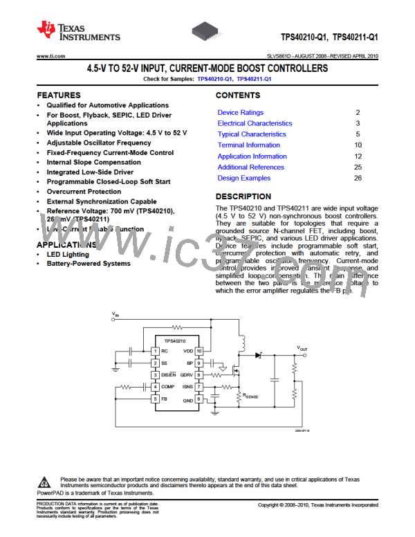
TPS40210-Q1, TPS40211-Q1
www.ti.com
SLVS861D –AUGUST 2008–REVISED APRIL 2010
Table 1. TPS40210 Design Example Specifications (continued)
PARAMETER
SYSTEM CHARACTERISTICS
CONDITIONS
MIN NOM MAX UNIT
fSW
hPK
h
Switching frequency
Peak efficiency
600
95%
94%
25
kHz
°C
in
VIN = 12 V, 0.2 A ≤ IOUT ≤ 2 A
VIN = 12 V, IOUT = 2 A
Full load efficiency
TOP
Operating temperature range
10 V ≤ VIN ≤ 14 V, 0.2 A ≤ IOUT ≤ 2 A
MECHANICAL DIMENSIONS
W
L
Width
1.5
1.5
0.5
Length
Height
h
Step-By-Step Design Procedure
Duty Cycle Estimation
The duty cycle of the main switching MOSFET is estimated using Equation 32 and Equation 33.
V
- V
+ V
24V -14V + 0.5V
24V + 0.5V
OUT
IN(max) FD
D
»
=
= 42.8%
MIN
V
+ V
OUT
FD
(32)
V
- V
+ V
24 V - 8 V + 0.5 V
24 V + 0.5 V
OUT
IN(min) FD
D
»
=
= 67.3%
MAX
V
+ V
OUT
FD
(33)
Using and estimated forward drop of 0.5 V for a Schottky rectifier diode, the approximate duty cycle is 42.8%
(minimum) to 67.3% (maximum).
Inductor Selection
The peak-to-peak ripple is limited to 30% of the maximum output current.
I
2
OUT(max)
I
= 0.3 ´
= 0.3 ´
= 1.05 A
Lrip(max)
1- D
1- 0.428
MIN
(34)
(35)
The minimum inductor size can be estimated using Equation 35.
V
1
14V
1
IN(max)
LMIN
»
´DMIN
´
=
´ 0.428´
= 9.5mH
ILrip(max)
fSW 1.05A
600kHz
The next higher standard inductor value of 10 mH is selected. The ripple current is estimated by Equation 36.
V
1
12 V
1
IN
IRIPPLE
»
´ D ´
=
´ 0.50 ´
= 1.02 A
L
fSW
10 mH
600kHz
(36)
(37)
V
1
8V
1
IN
I
»
´D´
=
´ 0.673´
= 0.89A
RIPPLE(Vinmin)
L
f
10mH
600kHz
SW
The worst-case peak-to-peak ripple current occurs at 50% duty cycle and is estimated as 1.02 A. Worst-case
RMS current through the inductor is approximated by Equation 38.
ö2
2
æ
ö2
2
I
æ
2
2
)
2
OUT(max)
1
12
1
1
ILrms
=
I
+
IRIPPLE
»
+
IRIPPLE(VINmin)
=
+
´ 0.817A = 6.13Arms
ç
ç
÷
÷
(
( )
(
12
(
)
)
( )
L avg
ç
÷
12
(
)
1- DMAX
1- 0.673
è
ø
è
ø
(38)
The worst case RMS inductor current is 6.13 Arms. The peak inductor current is estimated by Equation 39.
Copyright © 2008–2010, Texas Instruments Incorporated
Submit Documentation Feedback
27
Product Folder Link(s): TPS40210-Q1 TPS40211-Q1

 TI [ TEXAS INSTRUMENTS ]