TPS40200-Q1
www.ti.com
SLUS739D –SEPTEMBER 2006–REVISED JULY 2011
Soft-Start Capacitor
The soft-start interval is given (in pF) by:
tSS
CSS
=
´103
Where:
R = internal 105-kΩ charging resistor
æ
ç
ç
è
ö
÷
÷
ø
VSST
SST -1.4
R ´ ln
V
VCC = input voltage up to 8 V, where the charging voltage is
internally clamped to 8 V maximum
VOS = 700 mV, and (because the input voltage is 12 V)
VSST = 8 V
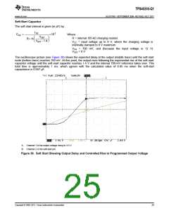
The oscilloscope picture (see Figure 39) shows the expected delay at the output (middle trace) until the soft-start
node (bottom trace) reaches 700 mV. At this point, the output rises following the exponential rise of the soft-start
capacitor voltage until the soft-start capacitor reaches 1.4 V and the internal 700-mV reference takes over. This
total time is approximately 1 ms, which agrees with the calculated value of 0.95 ms when the soft-start
capacitance is 0.047 μF.
A. Channel 1 is the output voltage rising to 3.3 V.
B. Channel 2 is the soft-start pin.
Figure 39. Soft Start Showing Output Delay and Controlled Rise to Programmed Output Voltage
Copyright © 2006–2011, Texas Instruments Incorporated
25

 TI [ TEXAS INSTRUMENTS ]