TPS40200-Q1
SLUS739D –SEPTEMBER 2006–REVISED JULY 2011
www.ti.com
Programming the Overcurrent Threshold Level
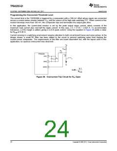
The current limit in the TSP40200 is triggered by a comparator with a 100-mV offset whose inputs are connected
across a current-sense resistor between VCC and the source of the high-side switching FET. When current in this
resistor develops more than 100 mV, the comparator trips and terminates the output gate drive.
In this application, the current-limit resistor is set by the peak output stage current, which consists of the
maximum load current plus one-half the ripple current. In this case, 2.5 + 0.125 = 2.625 A. To accommodate
tolerances, a 25% margin is added, giving a 3.25-A peak current. Using the equation in Figure 38 yields a value
for RILIM of 0.30 Ω.
Current sensing in a switching environment requires attention to both circuit board traces and noise pickup. In the
design shown, a small RC filter has been added to the circuit to prevent switching noise from tripping the
current-sense comparator. The requirements of this filter are board dependent but, with the layout used in this
application, no spurious overcurrent was observed.
VIN
RILIM
RF1
TPS40200
8
7
6
VDD
RF2
CF
ISNS
GDRV
0.1
ILIM =
RILIM
Figure 38. Overcurrent Trip Circuit for RF2 Open
24
Copyright © 2006–2011, Texas Instruments Incorporated

 TI [ TEXAS INSTRUMENTS ]