TPS40200-Q1
SLUS739D –SEPTEMBER 2006–REVISED JULY 2011
www.ti.com
In order to properly compensate this system, it is necessary to know the frequencies of its poles and zeros.
Step 1
The break frequency of the output capacitor is given by:
Where:
1
Fesr
=
C = the output capacitor
2pResr
C
RESR = the ESR of the capacitors
Because of the ESR of the output capacitor, this output filter has a single-pole response above the 1.8-kHz break
frequency of the output capacitor and its ESR. This simplifies compensation since the system becomes
essentially a single-pole system.
Step 2
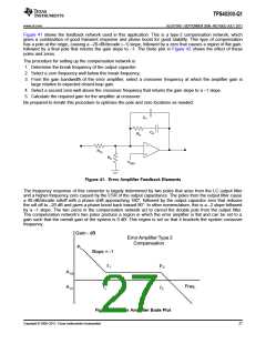
The first zero is place well below the 1.8-kHz break frequency of the output capacitor and its ESR. Phase boost
from this zero is shown in Figure 44.
1
Where:
fZ1
=
2pR8C8
R8 = 300 kΩ
C8 = 1500 pF
FZ1 = 354 Hz
Step 3
From a minimum gain bandwidth product of 1.5 MHz, and knowing it has a 20-dB/decade rolloff, the open-loop
gain of the error amplifier is 33 dB at 35 kHz. This approximate frequency is chosen for a crossover frequency to
keep the amplifier gain contribution to the overall system gain small, as well as following the convention of placng
the crossover frequency between 1/6 to 1/10 the 300 kHz switching frequency.
Step 4
The second pole is placed well above the 35-kHz crossover frequency.
1
Where:
fP2
=
× (C7 + C8)
2π ×C7 ×C8 ×R8
R8 = 300 kΩ
C7 = 10 pF
C8 = 1500 pF
fP3 = 53 kHz
28
Copyright © 2006–2011, Texas Instruments Incorporated

 TI [ TEXAS INSTRUMENTS ]