TMS3705
www.ti.com
11-07-22-003 – SCBS881B –JANUARY 2010–REVISED APRIL 2010
Power-
On
SLEEP
Approx. 2 ms after
TXCT goes low(4)
after approx. 2 ms
after approx. 100 ms
IDLE
TXCT is low
TXCT goes high
before 96ms
0.9 ms after TXCT goes low(2)
or approx. 4 ms after start of Receive
phase if no start bit is detected
or otherwise approx. 20 ms after
start of Receive phase
MCR Programming:
(3)
Write bits into
Mode Control Register
(5)
MCR bits received
RECEIVE Phase:
DIAGNOSIS Phase:
Frequency measurement
Transponder signal
demodulation
Start of Charge Phase
Perform diagnosis
FAIL
Data output to mC after
reception of start byte
Send diag. byte approx.
2 ms after leaving Idle state
(1)
Diag. byte sent
TXCT remains high for 1.6 ms
WRITE Phase(6):
CHARGE Phase:
TXCT goes high
Start of write phase
Frequency measurement
Program phase
Charge phase continues
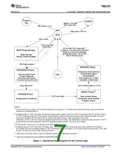
Notes :
(1) In SCI synchronous mode, this transition always occurs approx. 3 ms after leaving Idle state (diag. byte transmission
should be completed before).
(2)
ms.
A falling edge on TXCT interrupts the Receive phase after a delay of 0.9 ms. TXCT must remain low for at least 128
If TXCT is still low after the 0.9 ms delay, the basestation will go to Idle and directly to the Diagnosis phase one clock
cycle later (Dotted line(3)).No MCR can be written, noly default mode is fully supported in this case.
Otherwise, if TXCT returns to high and remains high during the delay, the basestation will stay in Idle and wait for TXCT
to go low (this will start properly a new MCR programming) or wait for 100 ms to go to Sleep.
(2)
(3) This transition only occurs in a special case (see note
)
(4) A falling edge on TXCT interrupts the Sleep state. Only default mode is fully supported when starting an operation
from Sleep with only one falling edge on TXCT (because of the 2 m s delay). For a proper M CR programming, TXCT has
to return to high and remain high during this delay.
(5)
Idle mode is the next state in case of undefined sataes ('fail safe state machine')
(6)
Frequency measurement only available for TMS3705A1DRG4
Figure 1. Operational State Diagram for the Control Logic
Copyright © 2010, Texas Instruments Incorporated
Submit Documentation Feedback
7

 TI [ TEXAS INSTRUMENTS ]